Microstrip patch antenna with reconfigurable directional diagram

A microstrip patch antenna and directional pattern technology, applied in the direction of antenna, radiating element structure, electrical components, etc., can solve the problems of few working modes, large cross-polarization, large antenna size, etc., and achieve small size, cross-polarization and other problems. The effect of small reduction and high gain

Inactive Publication Date: 2010-09-15
UNIV OF ELECTRONIC SCI & TECH OF CHINA
View PDF3 Cites 38 Cited by
  • Summary
  • Abstract
  • Description
  • Claims
  • Application Information

AI Technical Summary

Problems solved by technology

However, due to the use of dual-coaxial cable feed, the feed system has a serious impact on the antenna; the antenna is large in size, which is not conducive to high-frequency applications
[0004] The document "A Pattem Reconfigurable Microstrip Parasitic Array" (S. Zhang, G.H. Huff, J. Feng, and J. T. Bernhard IEEE TRANSACTIONS ON ANTENNAS AND PROPAGATION, VOL.52, NO.10, OCTOBER 2004) provides a new type of The pattern can be reconfigured as a microstrip antenna, which realizes beam scanning in thr

Method used


Image

  • Microstrip patch antenna with reconfigurable directional diagram
  • Microstrip patch antenna with reconfigurable directional diagram
  • Microstrip patch antenna with reconfigurable directional diagram

Examples


Embodiment Construction

[0017] The embodiments of the present invention are described in detail below in conjunction with the accompanying drawings: this embodiment is implemented on the premise of the technical solution of the present invention, and detailed implementation methods and specific operating procedures are provided, but the protection scope of the present invention is not limited to the following the described embodiment.

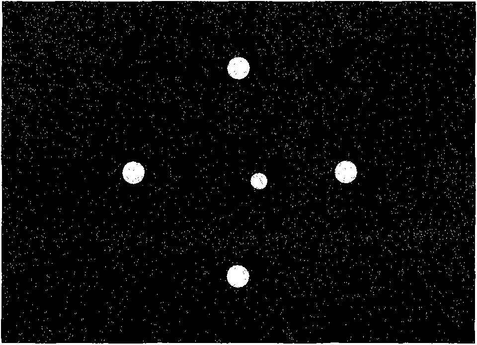
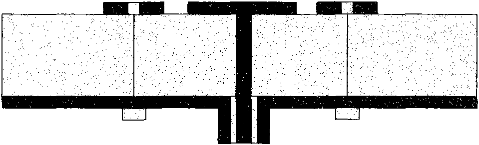
[0018] A pattern reconfigurable microstrip patch antenna, such as Figure 1 to Figure 3 As shown, it includes a metal ground plate on the lower surface of the dielectric board and a radiation patch on the upper surface of the dielectric board.

[0019] The radiation patch includes a square main radiation patch unit and four parasitic patch units at equal distances from the front, back, left, and right sides of the square main radiation patch unit; each parasitic patch unit includes two rectangular patches and a An electronic switch connected together with two rectangu...


PUM


Abstract

The invention relates to a microstrip patch antenna with a reconfigurable directional diagram, which belongs to the technical field of antennae. The microstrip patch antenna comprises a metal ground plate on the lower surface of a dielectric plate and a radiation patch on the upper surface of the dielectric plate, wherein the radiation patch consists of a square main radiation patch unit and four appended patch units with same distances from four directions of the square main radiation patch unit; each appended patch unit consists of two rectangular patches connected by an electronic switch; and each electronic switch is respectively controlled by a switch controller. Different switch combinations control different appended patches to perform energy radiation so that a plurality of directional diagrams with multiple working modes can be realized. Meanwhile, the invention has the characteristics of little cross polarization, small size and high gain. The microstrip patch antenna is applicable to different antenna arrays to realize beam forming and scanning.

Description

technical field [0001] The invention belongs to the technical field of antennas, and relates to a microstrip patch antenna, in particular to a reconfigurable microstrip patch antenna with a pattern. Background technique [0002] With the rapid development of radar technology and aerospace technology, the classic single-mode (single pattern) antenna has been increasingly unable to meet the requirements of radar and aircraft for beam forming, beam electronically controlled fast scanning, etc., which makes the pattern can be Reconfigurable antennas emerged as the times require, and have received more and more attention and development. At present, there are many kinds of reconfigurable antenna elements with pattern, but there are common problems such as few optional modes, large cross polarization, and unsatisfactory beam width. The microstrip patch pattern reconfigurable antenna is an important part of the pattern reconfigurable antenna, which has the advantages of easy proce...

Claims


Application Information

Patent Timeline
IPC IPC(8): H01Q13/08H01Q1/38H01Q3/00
Inventor 杨雪松钱昊
Owner UNIV OF ELECTRONIC SCI & TECH OF CHINA
Why Eureka
Try Eureka