An LTCC stack coupled feed circularly polarized microstrip patch antenna

A microstrip patch antenna, coupled feed technology, applied in the antenna unit combination, antenna, antenna coupling and other directions with different polarization directions, can solve the problem that the circular polarization effect of the antenna is not very good, the antenna axis ratio parameter is poor, and the The problem of high precision requirements for chip cutting corners, etc., can achieve the effect of widening bandwidth, improving antenna performance, and reducing antenna size.

Inactive Publication Date: 2011-12-14
UNIV OF ELECTRONICS SCI & TECH OF CHINA
View PDF5 Cites 35 Cited by
  • Summary
  • Abstract
  • Description
  • Claims
  • Application Information

AI Technical Summary

Problems solved by technology

Although this method is more convenient to implement, the circular polarization effect of the antenna is not very good, the antenna axis ratio parameter is poor, and the dimensional accuracy of the chip cutting angle is very high.

Method used


Image

  • An LTCC stack coupled feed circularly polarized microstrip patch antenna
  • An LTCC stack coupled feed circularly polarized microstrip patch antenna
  • An LTCC stack coupled feed circularly polarized microstrip patch antenna

Examples


Embodiment Construction

[0022] The present invention will be described in further detail below with reference to a preferred implementation and the accompanying drawings, but the implementation of the present invention is not limited thereto.

[0023] The center frequency point of the preferred embodiment microstrip patch antenna is 1.268GHz, and it is a BD-2 type microstrip receiving patch antenna. The present invention can realize a microstrip patch antenna with an impedance bandwidth exceeding 60MHz in a section thickness of 3mm. And the axial ratio of the antenna may be less than 1.5.

[0024] The main structure of this preferred embodiment includes:

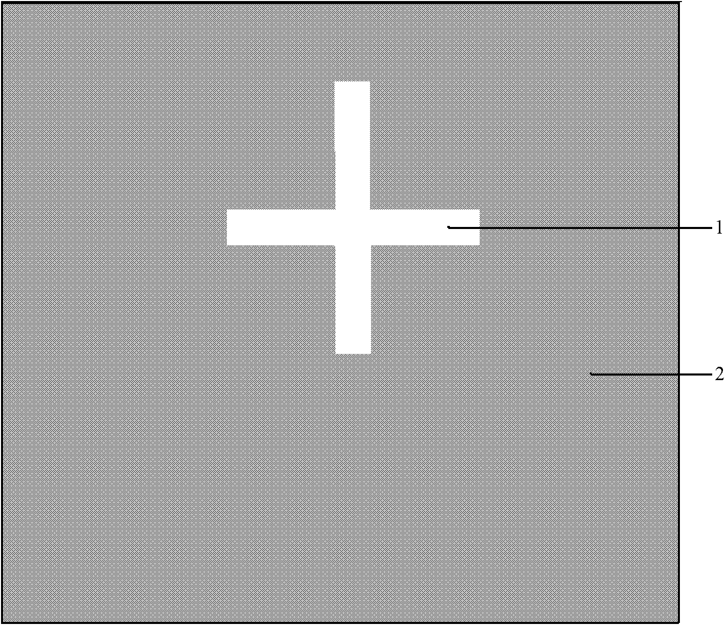
[0025] Feed layer dielectric substrate: The substrate is made of 15 LTCC cast ceramic diaphragms with a thickness of 100 μm, and the dielectric constant of the cast ceramic diaphragm is 14. Except for a symmetrical "cross" shaped hollow area on the upper surface of the substrate, the other parts are all printed with silver paste as a grounding met...


PUM


Abstract

The invention relates to an LTCC laminated coupling feed circularly polarized microstrip patch antenna, which belongs to the technical field of antennas. Including the feeding layer and the radiation layer dielectric substrate; the upper surface of the feeding layer dielectric substrate is a grounding metal layer with a "cross" shaped hollow area, and the lower surface has a feeding circuit and a shielding metal layer insulated from the feeding circuit; the feeding circuit Divide and phase-shift the incoming excitation signal into four branch excitation signals with equal amplitude and 90° phase difference, and couple to the radiation metal layer through the "cross" hollow area; the ground metal layer and the shielding metal layer pass through The evenly distributed metallized through holes are connected to each other; the radiation metal layer on the upper surface of the radiation layer dielectric substrate is a fractal pattern structure. The patches are formed iteratively in this way. The invention has the advantages of low profile, wide frequency band, circular polarization and miniaturization.

Description

Technical field: [0001] The invention belongs to the technical field of antennas, in particular to a low-profile microstrip fractal patch antenna for radio reception. Background technique: [0002] Microstrip patch antenna has many advantages such as small size, light weight, thin profile, easy conformal, etc. It is widely used in satellite positioning, wireless communication, remote sensing, aerospace and other fields. In airborne or missile-borne applications, the performance requirements of microstrip patch antennas are particularly emphasized for their low profile, wide frequency band and circular polarization. However, the input impedance of the microstrip patch antenna is very sensitive to changes with frequency, resulting in a narrow impedance bandwidth. The current microstrip patch antennas generally use organic dielectric materials or ceramic materials as substrates. In order to expand the bandwidth of microstrip patch antennas, common methods include increasing th...

Claims


Application Information

Patent Timeline
Patent Type & Authority Applications(China)
IPC IPC(8): H01Q1/38H01Q1/48H01Q1/52H01Q13/08H01Q21/24
Inventor 苏桦唐晓莉张怀武李旭哲钟智勇荆玉兰
Owner UNIV OF ELECTRONICS SCI & TECH OF CHINA
Why Eureka
Try Eureka