
Dual spindle piezoelectric detection gyroscope possessing magnetostriction vibrator

A magnetostrictive and electrical detection technology, applied in the field of micro gyroscopes, can solve the problems of difficult and accurate realization of circular motion, high control requirements, and increased angular velocity detection error, etc., to achieve processing technology, less coupling interference, and impact resistance strong effect

Inactive Publication Date: 2010-10-20
SHANGHAI JIAOTONG UNIV
View PDF5 Cites 2 Cited by
  • Summary
  • Abstract
  • Description
  • Claims
  • Application Information

AI Technical Summary

Problems solved by technology

[0004] This technology has the following disadvantages: First, the drive circuit requires multiple phase shifts, and some drive circuits also include amplitude detection circuits and AGC circuits, which have high requirements for control, and the circuits are complex, with large interference and noise, and it is difficult to obtain ideal drive signals.
Secondly, by applying four-phase driving signals with different phases to four different electrodes to make the piezoelectric body itself generate circular motion as a reference motion, regular circular motion is difficult to achieve accurately, which increases the error of angular velocity detection
To ensure that the piezoelectric body rotates to obtain high-speed circular motion, the power consumption is large

Method used


Image

  • Dual spindle piezoelectric detection gyroscope possessing magnetostriction vibrator
  • Dual spindle piezoelectric detection gyroscope possessing magnetostriction vibrator

Examples


Embodiment Construction

[0014] The embodiments of the present invention are described in detail below in conjunction with the accompanying drawings: this embodiment is implemented on the premise of the technical solution of the present invention, and detailed implementation methods and specific operating procedures are provided, but the protection scope of the present invention is not limited to the following the described embodiment.

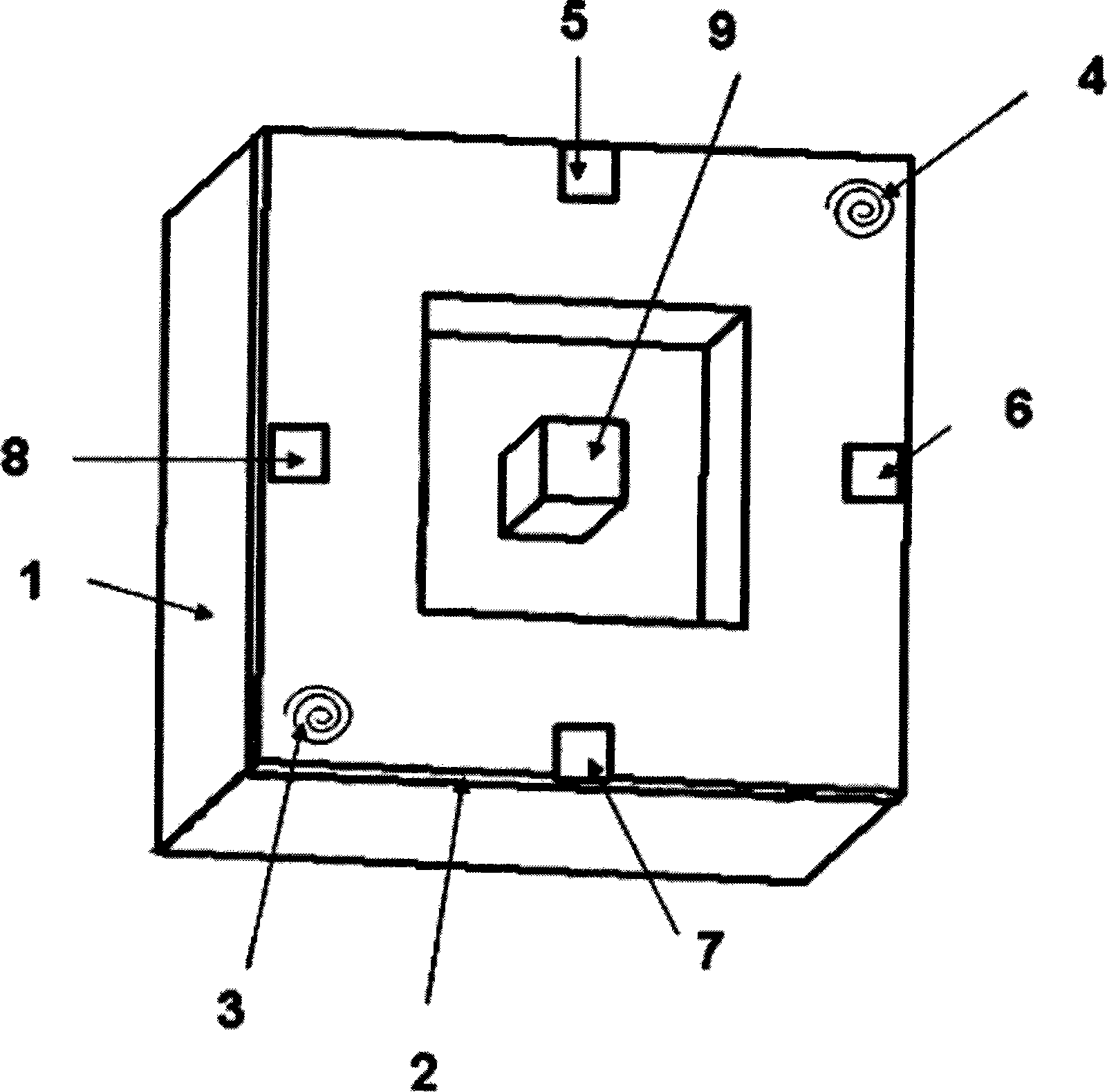
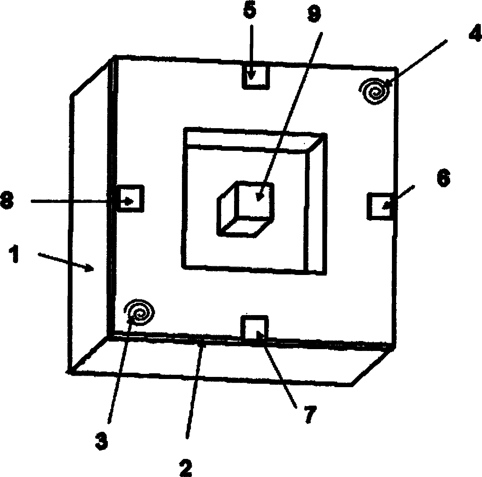
[0015] Such as figure 1 As shown, this embodiment consists of a magnetostrictive vibrator 1, an upper surface piezoelectric film 2, a lower left driving coil 3, an upper right driving coil 4, an upper output electrode 5 on the upper surface, an output electrode 6 on the upper right side, and an upper surface The lower output electrode 7, the left output electrode 8 on the upper surface, the cantilever beam 9 on the upper surface, and the cantilever beam on the lower surface.

[0016] The material of the magnetostrictive vibrator 1 is a conductive magnetostrictive mat...


PUM


Abstract

A dual axis piezoelectric detection gyroscope with a magnetostrictive vibrator in the micro electromechanical technical field comprises a magnetostrictive vibrator, a driving coil, an output electrode and a cantilever beam. The magnetostrictive vibrator has a structure that the two square surfaces of a cuboid are provided with square-hole holes, and the inner boundary and the outer boundary of the square-hole shape are squares. The vibration of the magnetostrictive vibrator under special model is regarded as reference vibration; the magnetostrictive vibrator in the model has special positionsin both directions in which the moving directions on an upper surface and a lower surface are opposite. When the outside world has angular velocity, Coriolis force with opposite direction is generated on the opposite position of the moving direction to enable piezoelectric film to deform and generate internal stress, and the angular velocity of the outside dual axis is detected by the electric potential generated on the output electrode. The dual axis piezoelectric detection gyroscope has the advantages of simple structure, strong shock resistance, convenient fixing, sensitive dual axis detection, weak coupling interference between the reference vibration and the detection signal and power consumption saving owing to being free of high-speed rotation.

Description

technical field [0001] The invention relates to a micro-gyroscope in the field of micro-electromechanical technology, in particular to a biaxial piezoelectric detection gyroscope with a magnetostrictive vibrator. Background technique [0002] Gyroscope is the core device of attitude control and inertial guidance. The development of inertial technology and the improvement of guidance requirements for satellites and missiles require gyroscopes to develop in the direction of low power, long life, small size, and adaptability to various harsh environments. [0003] After searching the literature of the prior art, it was found that the Chinese patent "Piezoelectric Gyro Element and Piezoelectric Gyroscope" (patent application number: 200510131905.3) mentions that the structure of the prismatic vibrating body of the piezoelectric material can be used to detect the 2-axis Angular velocity in the direction. One end of a prism-shaped piezoelectric vibrator with a rectangular cross-s...

Claims


Application Information

Patent Timeline
Patent Type & Authority Patents(China)
IPC IPC(8): G01C19/5705G01C19/56
Inventor 张卫平卢奕鹏陈文元
Owner SHANGHAI JIAOTONG UNIV
Learn More