Low-loss dual polarized antenna for satcom and polarimetric weather radar

a dual-polarized, low-loss technology, applied in the direction of resonant antennas, antenna adaptation in movable bodies, radiating element structural forms, etc., can solve the problem that the electromagnetic field cannot propaga

Active Publication Date: 2008-10-14
ROCKWELL COLLINS INC
View PDF6 Cites 36 Cited by
  • Summary
  • Abstract
  • Description
  • Claims
  • Application Information

AI Technical Summary

Benefits of technology

[0009]Accordingly, the present invention is directed to a low-loss, dual polarized antenna. In general, the invention applies to systems where a microstrip patch antenna is combined with a waveguide for the transmission or reception of electromagnetic signals.

Problems solved by technology

If the waveguide is too narrow or the frequency is too low (i.e. the wavelength is too long), the electromagnetic fields cannot propagate.
Airborne TV antenna systems present a unique design challenge.

Method used


Image

  • Low-loss dual polarized antenna for satcom and polarimetric weather radar
  • Low-loss dual polarized antenna for satcom and polarimetric weather radar
  • Low-loss dual polarized antenna for satcom and polarimetric weather radar

Examples


Embodiment Construction

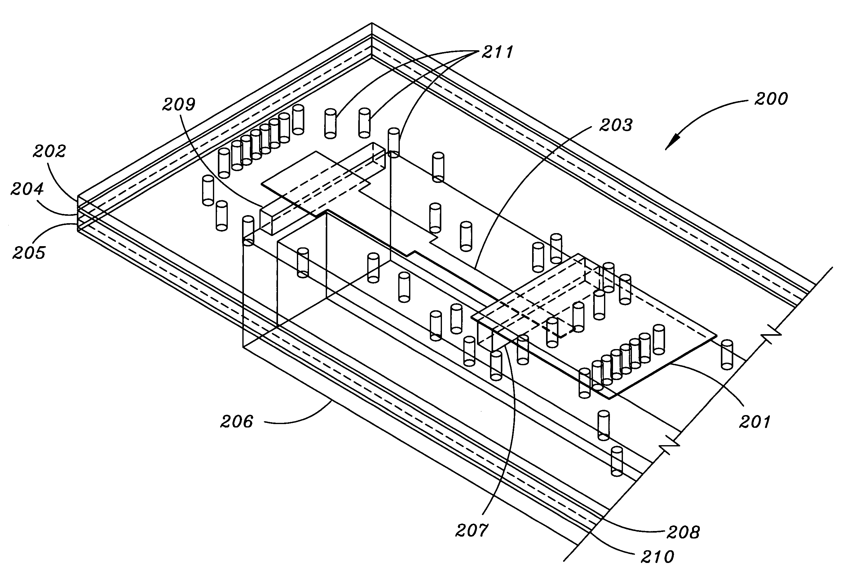
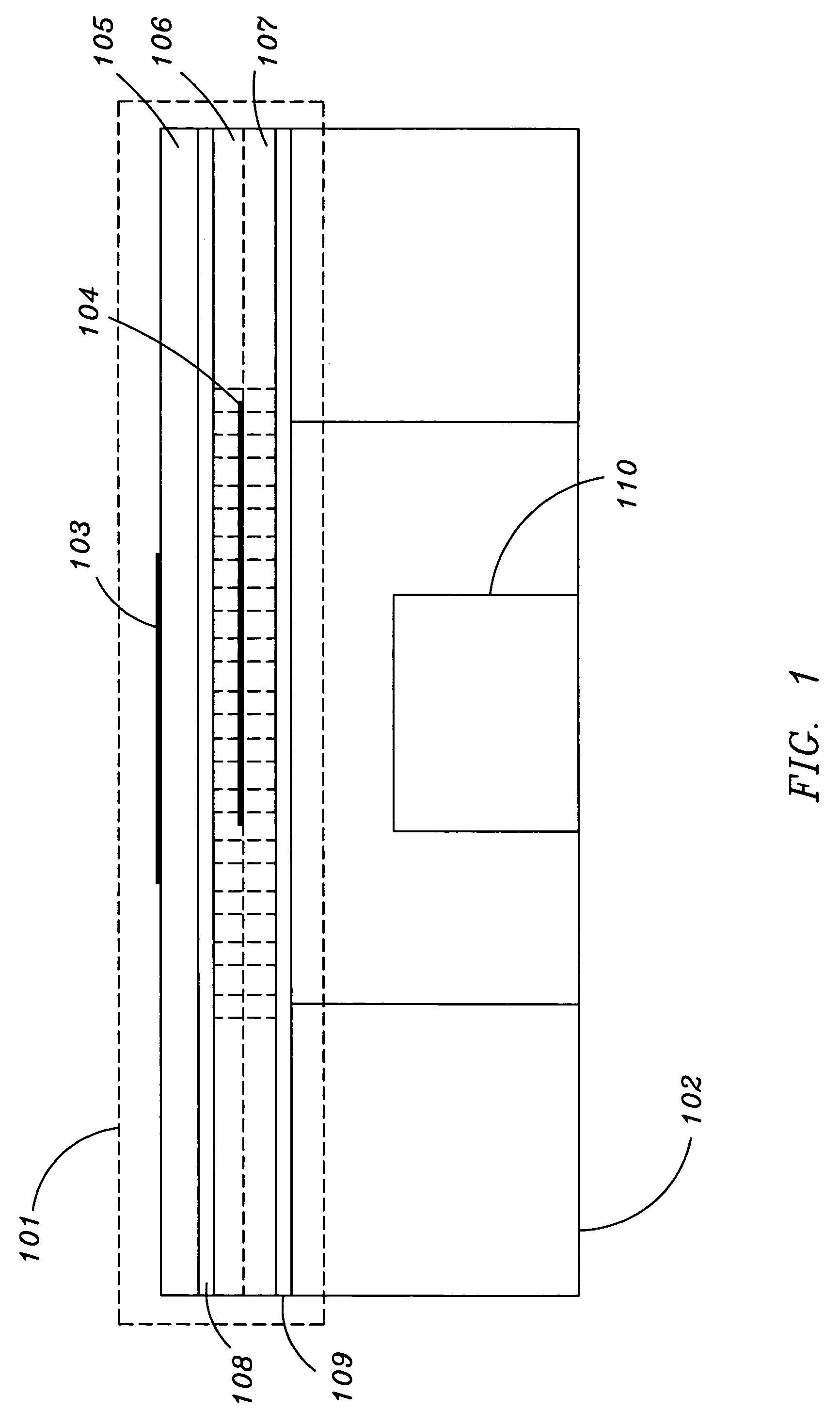
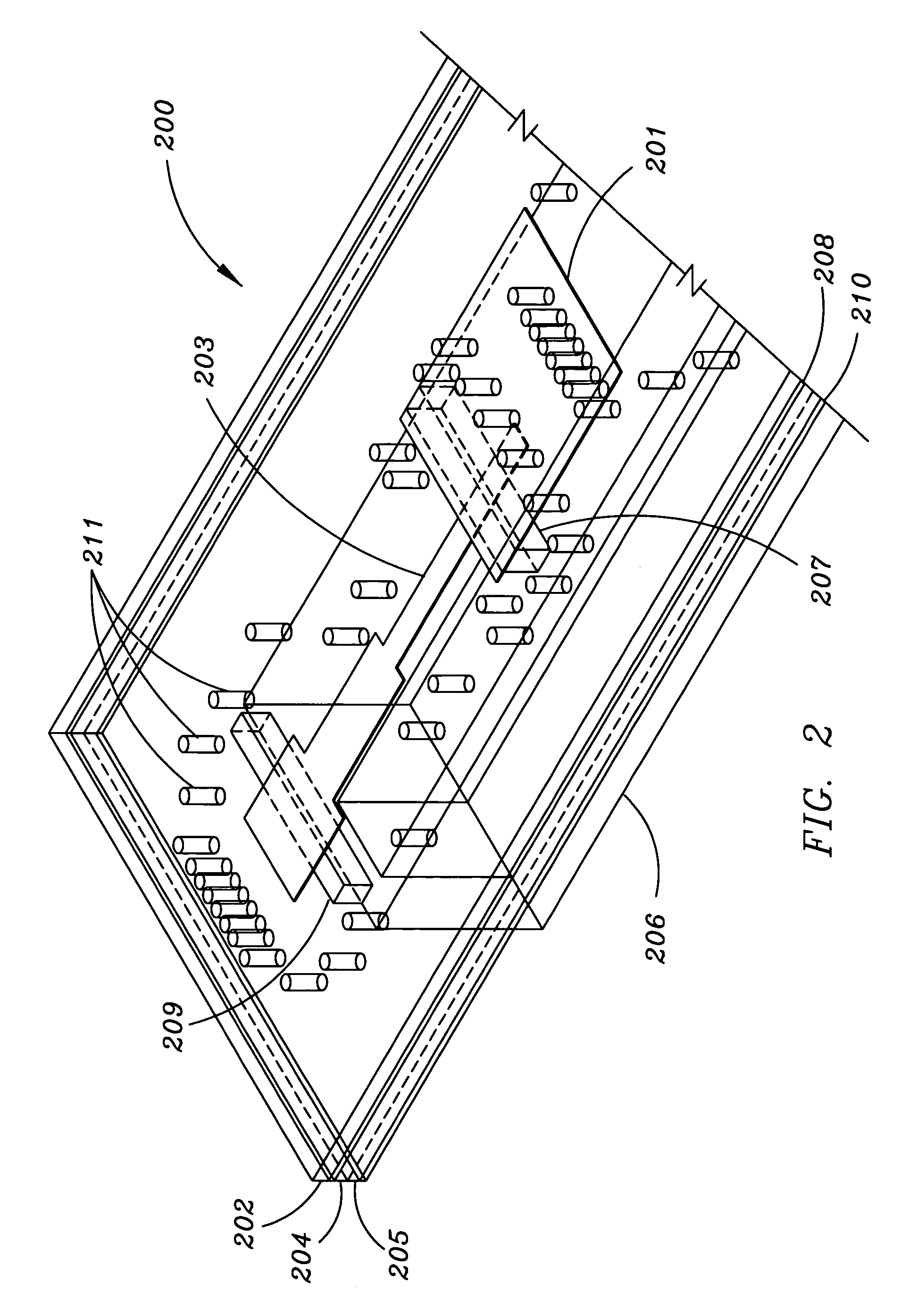
[0021]The following discussion is presented to enable a person skilled in the art to make and use the present teachings. Various modifications to the illustrated embodiments will be readily apparent to those skilled in the art, and the generic principles herein may be applied to other embodiments and applications without departing from the present teachings. Thus, the present teachings are not intended to be limited to embodiments shown, but are to be accorded the widest scope consistent with the principles and features disclosed herein. The following detailed description is to be read with reference to the figures, in which like elements in different figures have like reference numerals. The figures, which are not necessarily to scale, depict selected embodiments and are not intended to limit the scope of the present teachings. Skilled artisans will recognize the examples provided herein have many useful alternatives and fall within the scope of the present teachings. Reference wil...


PUM


Abstract

The present invention is a low-loss polarized antenna for satellite communications and polarimetric weather radar. The antenna may comprise: (a) a microstrip patch antenna, (b) a waveguide, and (c) a coupling interface between the antenna and waveguide. The microstrip patch antennas may individually comprise: (i) a patch radiator having a defined area, and (ii) an associated microstrip.
In a further embodiment of the invention, an antenna array is presented. The antenna array may comprise: (a) a plurality of microstrip antennas, and (b) a plurality of waveguides. The antenna array may further comprise: (c) a waveguide combiner. The microstrip patch antennas may individually comprise: (i) a patch radiator having a defined area, and (ii) an associated microstrip.
In still a further embodiment of the invention, a method for the manufacturing of an antenna is presented. The method may comprise the step: (a) operably coupling a microstrip patch antenna to a waveguide.

Description

FIELD OF THE INVENTION[0001]This invention relates generally to the transmission and reception of radio frequency signals and, more particularly to a low-profile, low-loss antenna apparatus.BACKGROUND OF THE INVENTION[0002]In many telecommunications applications, microstrip antennas are employed. There are several types of microstrip antennas (also known as printed antennas), the most common of which is the microstrip patch antenna. A microstrip patch antenna is a narrowband, wide-beam antenna fabricated by etching an antenna element pattern in metal trace bonded to an insulating substrate. Because such antennas may be low profile, mechanically rugged and conformable, they are often employed on aircraft and spacecraft, or are incorporated into mobile radio communications devices.[0003]Microstrip antennas are also relatively inexpensive to manufacture and design because of the simple 2-dimensional physical geometry. An advantage inherent to patch antennas is the ability to either tra...

Claims


Application Information

Patent Timeline
Patent Type & Authority Patents(United States)
IPC IPC(8): H01Q1/38H01Q13/10
CPCH01Q1/28H01Q1/38H01Q21/0043H01Q21/065
Inventor PAULSEN, LEE M.CHEN, DANIEL N.WEST, JAMES B.HERTING, BRIAN J.
Owner ROCKWELL COLLINS INC
Why Eureka
Try Eureka