High efficiency bridgeless PFC power converter

a power converter and bridgeless technology, applied in the field of power converters, can solve the problems of reducing the circuit efficiency the power consumption of the conventional pfc power converter, and achieve the effects of reducing the number of semiconductor devices, high efficiency, and good emi performan

Active Publication Date: 2012-06-12
SEMICON COMPONENTS IND LLC
View PDF4 Cites 23 Cited by
  • Summary
  • Abstract
  • Description
  • Claims
  • Application Information

AI Technical Summary

Benefits of technology

[0005]The present invention provides a bridgeless PFC power converter with high efficiency and good EMI performance. As compared with the conventional PFC power converter, the bridgeless PFC power converter reduces the number of semiconductor devices in any given conduction path to reduce the power loss for improving the circuit efficiency. Furthermore, the bridgeless PFC power converter of the present invention senses an output of the power supply to provide a light-load signal to disconnect the EMI filter during a light-load of the PFC power converter for power saving.
[0006]The bridgeless PFC power converter according to the present invention comprises a first inductor coupled from a first input-terminal to a first transistor. A second inductor is coupled from a second input-terminal to a second transistor. A first diode is coupled from the first transistor to an output capacitor. A second diode is coupled from the second transistor to the output capacitor. The first transistor, the second transistor and the output capacitor are further coupled to a ground terminal. A control circuit is coupled to the output capacitor, first input-terminal and the second input terminal to receive a feedback signal, a first-input signal and a second-input signal. The control circuit is coupled to the first transistor and the second transistor for detecting a first-current signal and a second-current signal. The control circuit generates a first-switching signal and a second-switching signal to control the first transistor and the second transistor in response to the feedback signal, the first-input signal, the second-input signal, the first-current signal and the second-current signal. The second-switching signal will turn on the second transistor when the first-switching signal switches the first transistor, and the first-switching signal will turn on the first transistor for achieving high efficiency when the second-switching signal switches the second transistor.
[0007]Further, the bridgeless PFC power converter of the present invention further comprises a first capacitor coupled from the first input-terminal to the ground terminal through a third transistor. A second capacitor is coupled from the second input-terminal to the ground terminal through a fourth transistor. The control circuit further generates a light-load signal to turn off the third transistor and the fourth transistor for saving power during the light-load of the PFC power converter. Besides, the first transistor and the second transistor are sense transistors. Each sense transistor has a sense-terminal to output a current signal, the magnitude of the current signal is corrected to a current flowed through the sense transistor.

Problems solved by technology

Therefore, the power consumption of the conventional PFC power converter is high so as to reduce circuit efficiency of the conventional PFC power converter.

Method used


Image

  • High efficiency bridgeless PFC power converter
  • High efficiency bridgeless PFC power converter
  • High efficiency bridgeless PFC power converter

Examples


Embodiment Construction

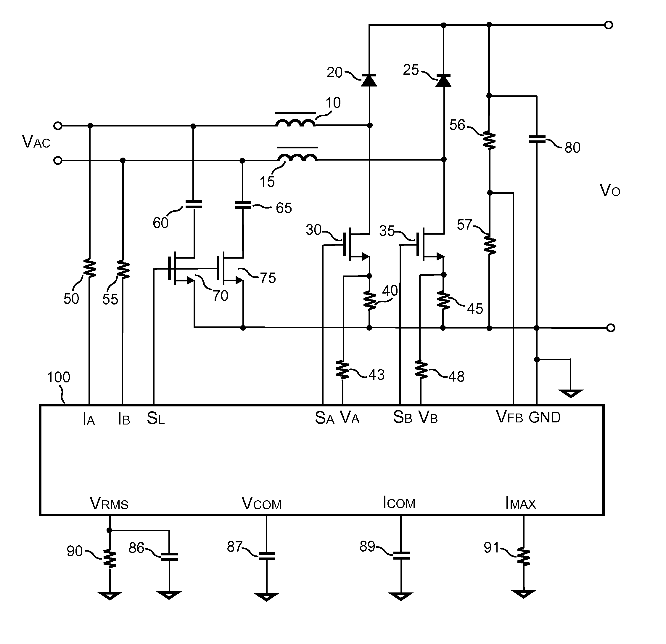
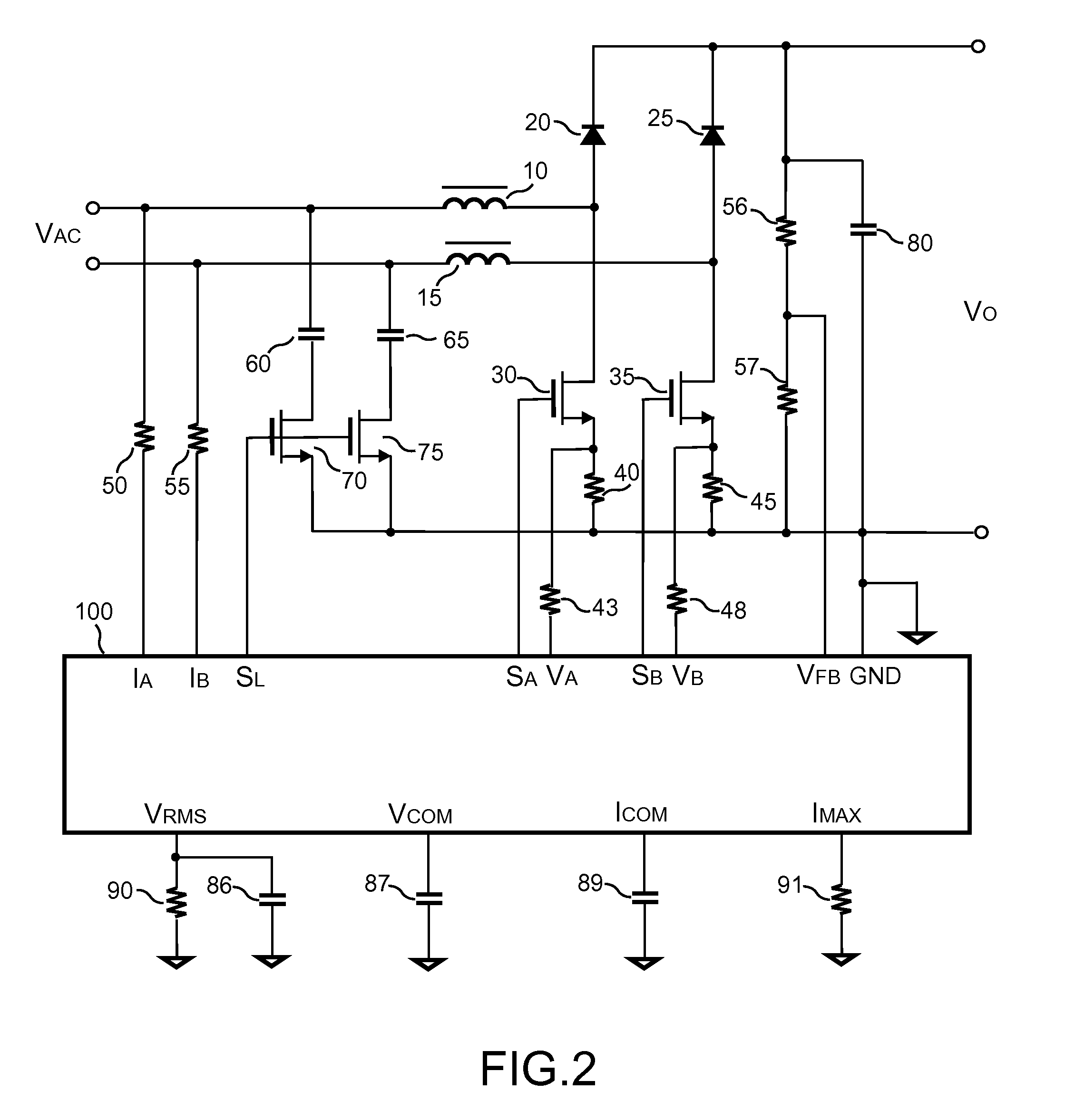
[0020]FIG. 2 shows the circuit schematic illustrating one embodiment of a PFC (Power Factor Correction) power converter according to the present invention. It includes a first inductor 10 coupled from a first input-terminal to a first transistor 30. A second inductor 15 is coupled from a second input-terminal to a second transistor 35. The first input-terminal and the second input-terminal receive an input voltage VAC. A first diode 20 is coupled from the first transistor 30 to an output capacitor 80. The output capacitor 80 is further coupled between an output terminal of power converter and a ground terminal for outputting an output voltage VO. A second diode 25 is coupled from the second transistor 35 to the output capacitor 80. The first transistor 30 and the second transistor 35 are further coupled to the ground terminal. A first capacitor 60 is coupled from the first input-terminal to the ground terminal through a third transistor 70. A second capacitor 65 is coupled from the ...


PUM


Abstract

A bridgeless PFC power converter comprises a first inductor and a second inductor coupled from a first input-terminal and a second input-terminal to a first transistor and a second transistor. A first diode and a second diode are coupled from the first transistor and the second transistor to an output capacitor. A first capacitor and a second capacitor are coupled from the input-terminals to the ground terminal through a third transistor and a fourth transistor. A control circuit generates a first-switching signal and a second-switching signal to control the first transistor and the second transistor. The second-switching signal will turn on the second transistor when the first-switching signal switches the first transistor. The first-switching signal will turn on the first transistor when the second-switching signal switches the second transistor. The control circuit turns off the third transistor and the fourth transistor during the light-load of the PFC power converter.

Description

BACKGROUND OF THE INVENTION[0001]1. Field of Invention[0002]The present invention relates to power converters, and more particularly, to the PFC power converters.[0003]2. Description of Related Art[0004]The purpose of Power Factor Correction (PFC) is to correct a line-input current of a power supply. The line-input current of the power supply corrected by PFC power converter generates a sinusoidal input current which is in phase with a line voltage. Most conventional PFC techniques incorporate a boost topology as shown in FIG. 1. The boost PFC power converter including a bridge rectifier has one MOSFET and five diodes. In addition, there are three semiconductor devices in the current conduction path. Therefore, the power consumption of the conventional PFC power converter is high so as to reduce circuit efficiency of the conventional PFC power converter.SUMMARY OF THE INVENTION[0005]The present invention provides a bridgeless PFC power converter with high efficiency and good EMI per...

Claims


Application Information

Patent Timeline
Patent Type & Authority Patents(United States)
IPC IPC(8): H02M7/219G05F1/70H02M1/42
CPCH02M1/4208H02M2001/123H02M1/4225Y02B70/126Y02B70/10Y02P80/10H02M1/123H02M1/0085
Inventor YANG, TA-YUNG
Owner SEMICON COMPONENTS IND LLC
Why Eureka
Try Eureka