Anti-vibration in-ceiling speaker system

a speaker system and ceiling technology, applied in the field of anti-vibration in ceiling speakers, can solve the problems of rattling or vibrating walls, unpleasant side effects, and little bass sound, and achieve the effect of reducing or eliminating rattling and facilitating bass sound, and reducing the rattling or vibrating of neighboring walls and ceiling surfaces

Inactive Publication Date: 2012-09-04
NEDELCU EUGEN
View PDF17 Cites 4 Cited by
  • Summary
  • Abstract
  • Description
  • Claims
  • Application Information

AI Technical Summary

Benefits of technology

[0005]Embodiments of the present anti-vibration in-ceiling speaker system provide a multi-way or full-range speaker system with a significant amount of bass sound capability, has the same aesthetic appearance of a traditional in-ceiling loudspeaker system, and yet also minimizes or eliminates rattling and vibrating of neighboring walls and ceiling surfaces. As such, it can be installed in a room along with traditional in-ceiling loudspeakers without visual distinction.

Problems solved by technology

However, known speaker assemblies mounted in this manner, such as that depicted in FIG. 15a, either provide little in the way of bass sounds or cause an unpleasant side effect by vibrating or rattling the walls and ceilings in which the system is mounted, as shown in FIG. 15b.
The movement of the driver's diaphragm necessarily results in movement of the surrounding environment of the woofer.
The vibrations also generate unwanted and out-of-phase sound, which distorts and otherwise interferes with the main sound signal the loudspeaker itself produces.
All this increases distortion levels in the bass frequencies of the loudspeaker system.
Another disadvantage to known speaker systems configured for providing significant bass sounds is the size of such systems.
Given the necessary large size of woofers, then, known speaker assemblies designed to provide a great deal of bass sound are generally large and therefore not conducive to in-wall or in-ceiling installations.
As such, they take up space in rooms or on furniture that could otherwise be put to another use.
Further, due largely because of the large size of woofers, speaker owners often place these bass-providing systems in corners of rooms or off to the side of a room, rather than near the middle of the room.
Placing the systems at these locations inevitably leads to increased vibration or rattling of close-by walls, floors, and furniture.
This system, however, is limited in the range of sound wave frequencies producible.
It further does not have the aesthetic appeal of traditional in-wall or in-ceiling tweeter loudspeakers.

Method used


Image

  • Anti-vibration in-ceiling speaker system
  • Anti-vibration in-ceiling speaker system
  • Anti-vibration in-ceiling speaker system

Examples


Embodiment Construction

[0028]While the system is susceptible of various modifications and alternative constructions, certain illustrated embodiments thereof have been shown in the drawings and will be described below in detail. It should be understood, however, that there is no intention to limit the system to the specific form disclosed, but, on the contrary, the anti-vibration in-ceiling speaker system is to cover all modifications, alternative constructions, and equivalents falling within the spirit and scope of the system as defined in the claims.

[0029]In the following description and in the figures, like elements are identified with like reference numerals. The use of “e.g.,”“etc.,” and “or” indicates non-exclusive alternatives without limitation unless otherwise noted. The use of “including” means “including, but not limited to,” unless otherwise noted.

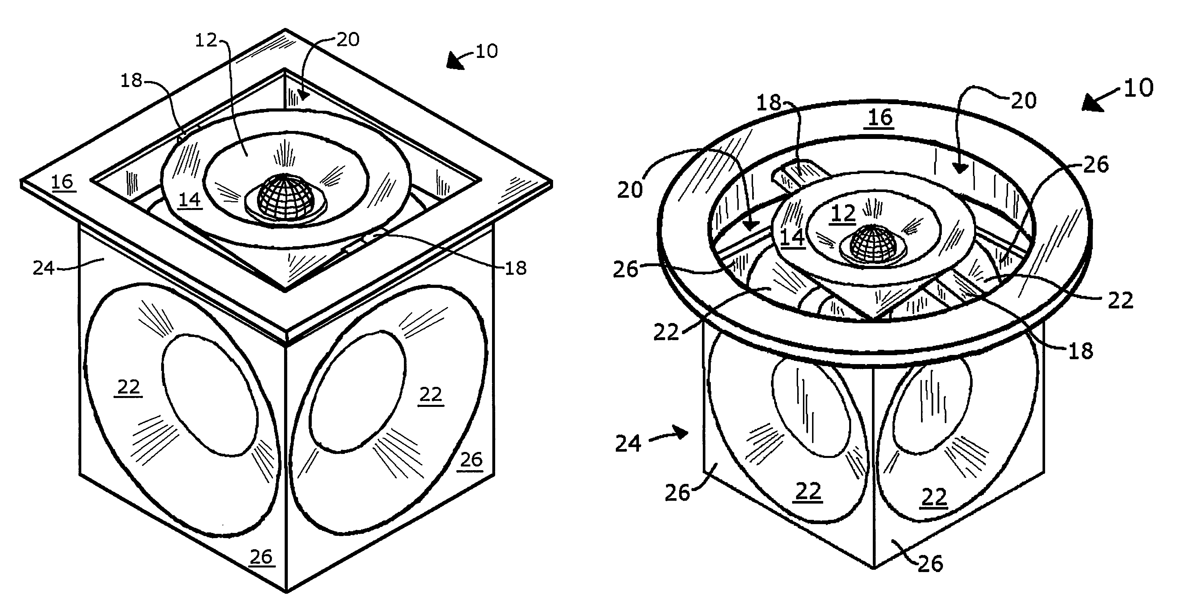
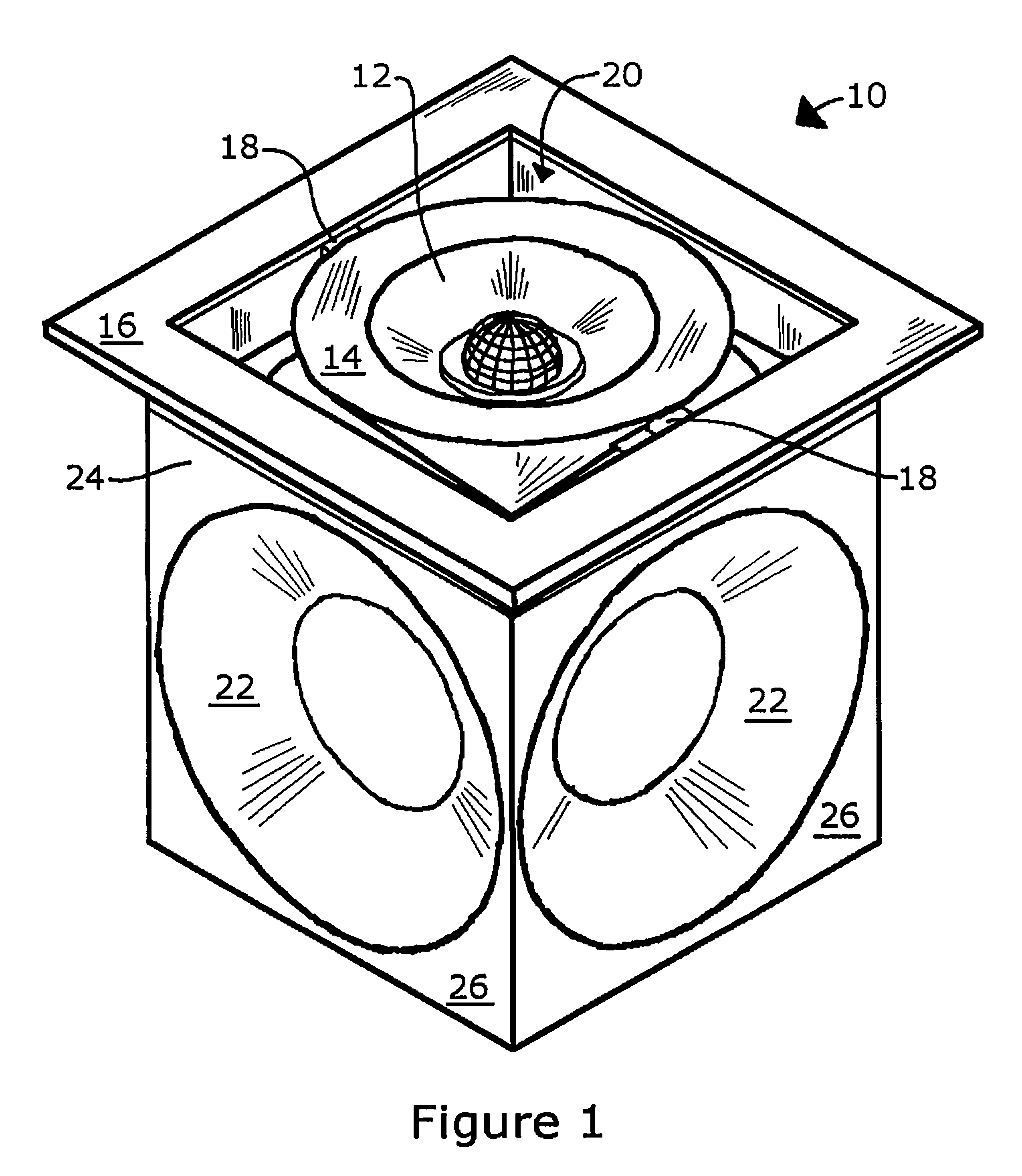
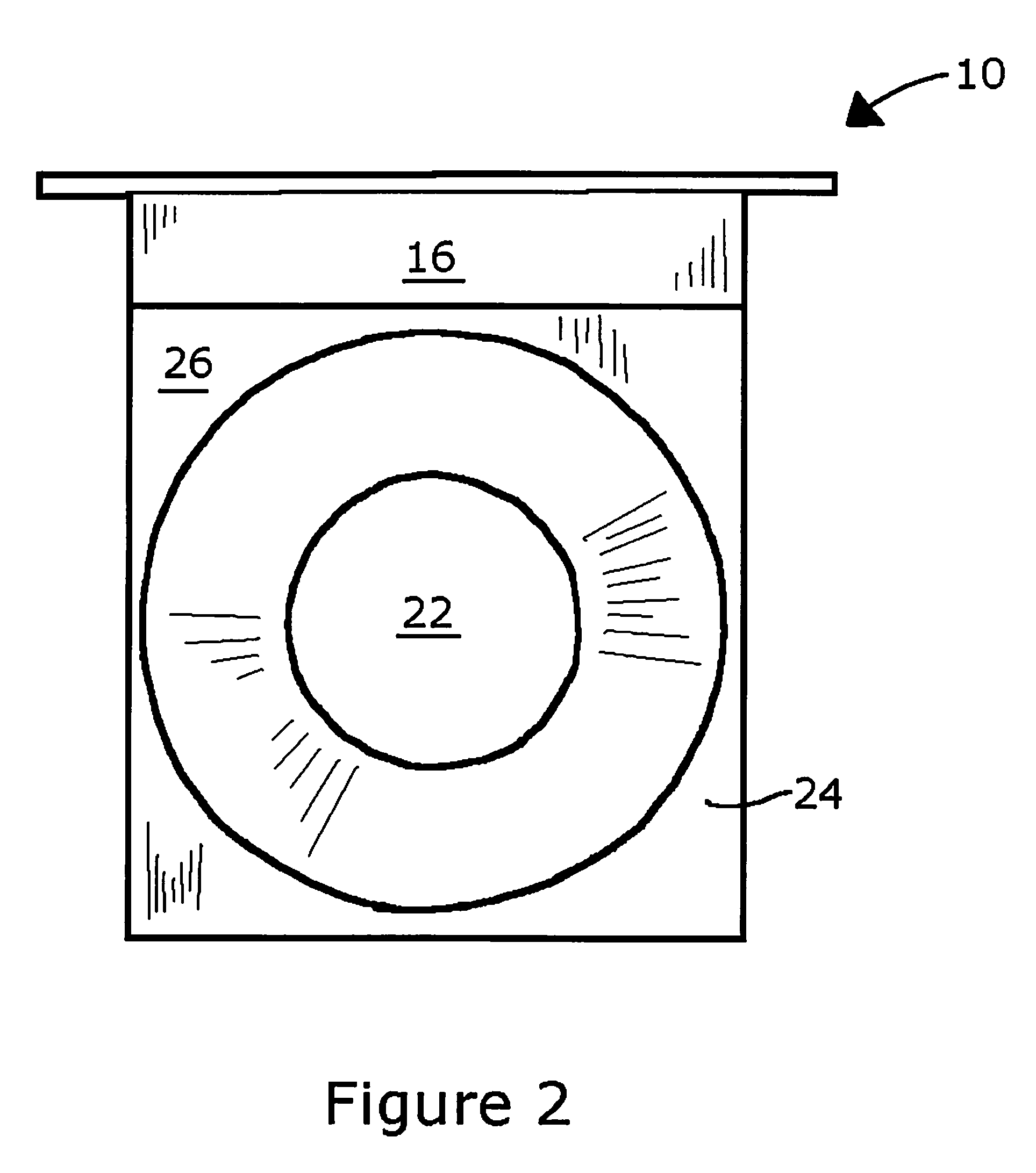
[0030]As shown in FIGS. 1 through 14, 15c, and 15d, for purposes of illustration, the anti-vibration in-ceiling speaker system 10 includes a woofer h...


PUM


Abstract

Disclosed is a speaker system for installation within a ceiling, wall, or other structure. The speaker system includes at least one pair of woofers housed by a woofer housing. The two woofers of each pair are oppositely arranged relative to one another so that the vibrations generated by each during operation are essentially neutralized or eliminated. Attached to the woofer housing is a mounting frame to which is attached a driver, such as a tweeter, a combination tweeter and midrange, or another woofer. This driver is perpendicularly arranged to a woofer pair. When installed, the woofers are positioned within the ceiling or other structure in which the system is installed.

Description

FIELD OF THE INVENTION[0001]The present anti-vibration in-ceiling speaker system generally relates to speaker systems, and more particularly to bass-producing speaker systems for installation within the ceiling of a room.BACKGROUND OF THE INVENTION[0002]In-wall and in-ceiling mounted speaker assemblies are quite popular. However, known speaker assemblies mounted in this manner, such as that depicted in FIG. 15a, either provide little in the way of bass sounds or cause an unpleasant side effect by vibrating or rattling the walls and ceilings in which the system is mounted, as shown in FIG. 15b. This is because bass-producing loudspeakers, i.e., woofers 22′, produce low-frequency sound waves through the back-and-forth movement of a driver's diaphragm, indicated by arrow 52′. The movement of the driver's diaphragm necessarily results in movement of the surrounding environment of the woofer. That is, the vibrations of the diaphragm transfer to the woofer's frame and eventually transfer ...

Claims


Application Information

Patent Timeline
Patent Type & Authority Patents(United States)
IPC IPC(8): H04R1/02
CPCH04R1/025H04R1/26H04R2201/021H04R2499/13
Inventor NEDELCU, EUGEN
Owner NEDELCU EUGEN
Why Eureka
Try Eureka