Control box

a control box and box body technology, applied in the field of control boxes, can solve the problems of shortening the service life of the battery, and unable to show the power state of controlled objects

Inactive Publication Date: 2012-10-30
POWERTECH INDAL
View PDF12 Cites 5 Cited by
  • Summary
  • Abstract
  • Description
  • Claims
  • Application Information

AI Technical Summary

Benefits of technology

[0009]The efficacy of the present invention is as follows: the control box of the present invention can achieve the efficacy of indicating the power states basing on the mechanical structure, without electricity, so that users can learn the current power state of the controlled object from the identifiable portion appearing in the display hole, and the service life of batteries of the control box can be prolonged.

Problems solved by technology

However, the power indicating lights not only consume much electric energy from the batteries of the remotes controllers, which shortens the service life of the batteries, but also cannot show power states of controlled objects when damaged.

Method used


Image

  • Control box
  • Control box
  • Control box

Examples


Embodiment Construction

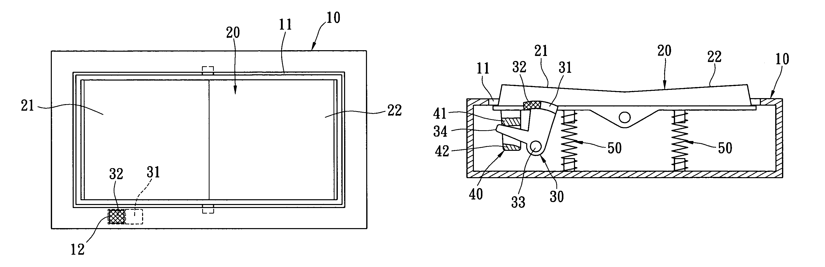
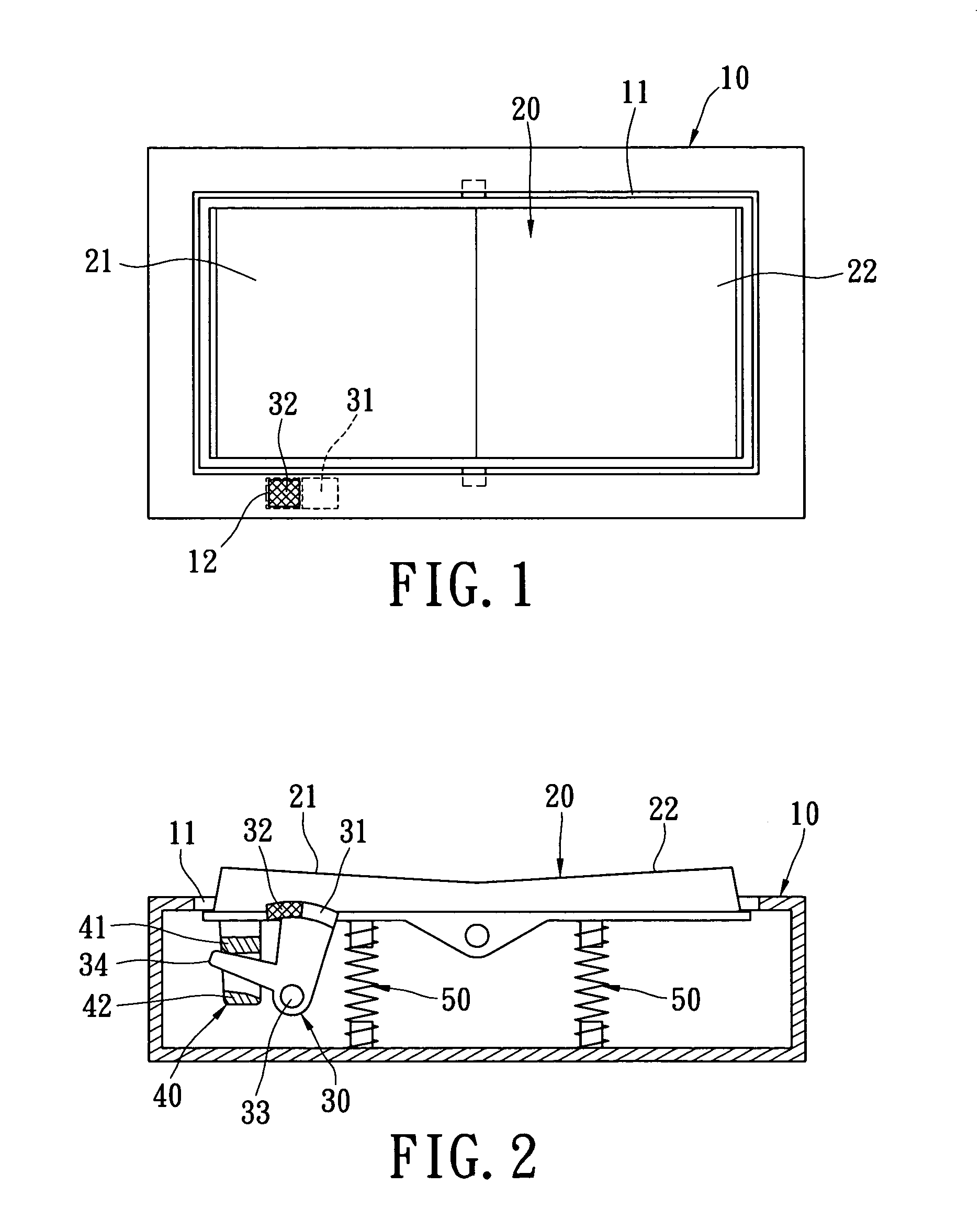
[0016]Please refer to FIG. 1 and FIG. 2 illustrating a control box. The control box may be, but no limited in, a remote controller with a function of turning on or turning off a controlled object. The control box includes a shell 10, a display hole 12, an active member 20, an indicating member 30, an interlinking member 40, and two elastic members 50. The shell 10 has an opening 11 connected with the inside of the shell 10. The display hole 12 is located in one side of the opening 11.

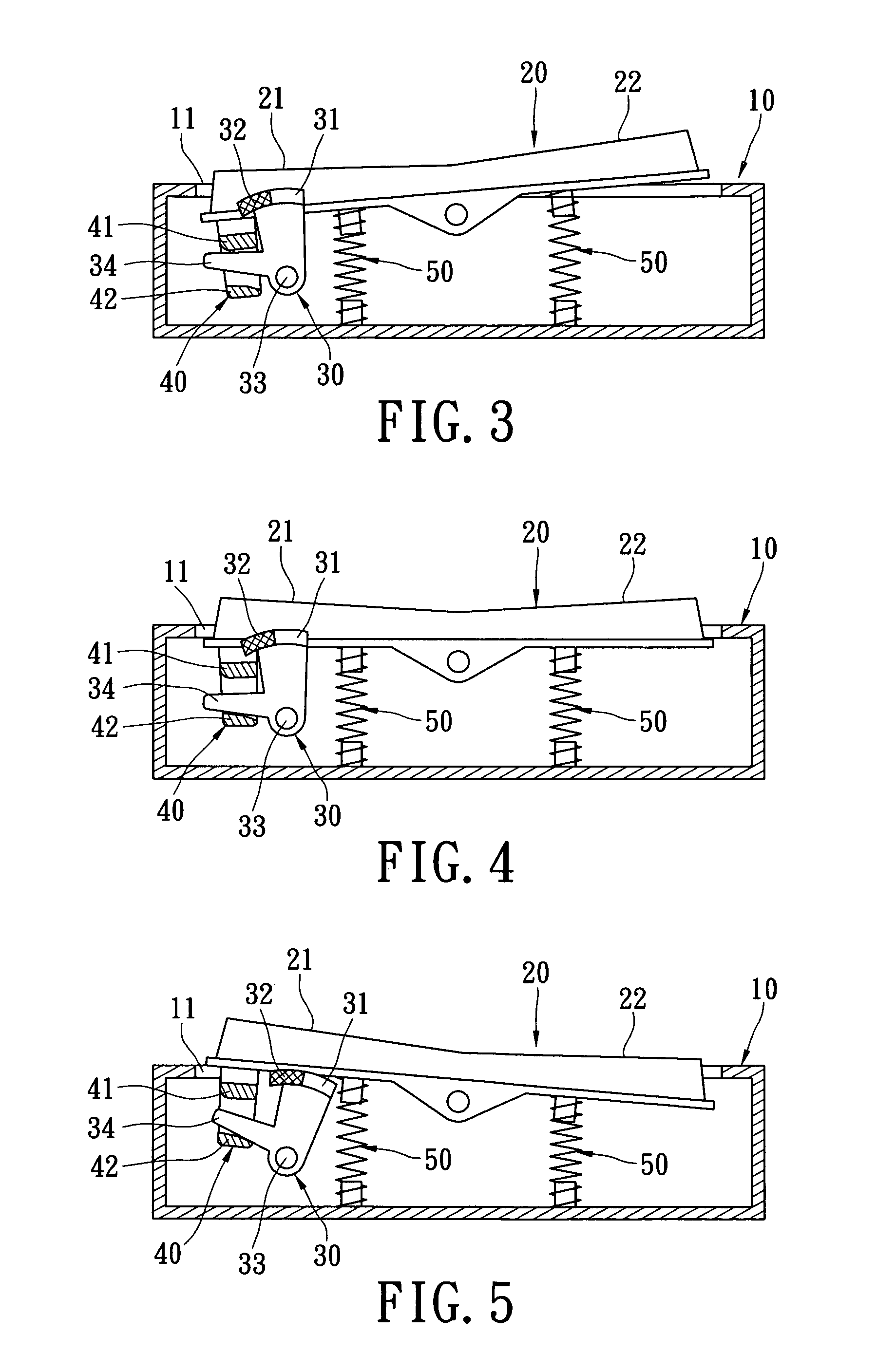
[0017]In the embodiment, the active member 20 is, but not limited in, a two-direction press button. The active member 20 has a turn-on end 21 and a turn-off end 22 for being pressed by users. The active member 20 is received in the opening 11 and pivotally connected with the shell 10. The pivoted portion between the active member 20 and the shell 10 is between the turn-on end 21 and the turn-off end 22 so that the turn-on end 21 and the turn-off end 22 of the active member 20 can seesaw, like two ends o...


PUM


Abstract

A control box includes a shell, a display hole, an active member, an indicating member and an interlinking member. The display hole is formed in the shell. The active member has a turn-on end and a turn-off end and is pivotally connected with the shell so as to seesaw. The indicating member is movably disposed in the shell and has a first identifiable portion and a second identifiable portion. The interlinking member is connected between the active member and the indicating member to drive the indicating member to move. Accordingly, when the active member seesaws under the effect of an external force, the indicating member is driven by the interlinking member to show the first identifiable portion or the second identifiable portion in the display hole.

Description

BACKGROUND OF THE INVENTION[0001]1. Field of the Invention[0002]The present invention relates to a control box, and more particularly to a control box which can indicate power states of a controlled object without electric drive.[0003]2. Description of Related Art[0004]General control box, such as remote controllers with batteries, have power indicating lights (for example, LED lights) and indicate power states of controlled objects based on changes of brightness or color of the power indicating lights.[0005]However, the power indicating lights not only consume much electric energy from the batteries of the remotes controllers, which shortens the service life of the batteries, but also cannot show power states of controlled objects when damaged.[0006]Hence, the inventors of the present invention believe that the shortcomings described above are able to be improved and finally suggest the present invention which is of a reasonable design and is an effective improvement based on deep ...

Claims


Application Information

Patent Timeline
Patent Type & Authority Patents(United States)
IPC IPC(8): G01D11/00
CPCH01H9/16H01H23/145
Inventor HSU, JUNG-HUIWU, CHENG-FENG
Owner POWERTECH INDAL
Why Eureka
Try Eureka