Hoisting machine including a measuring arrangement and elevator system containing the same

a technology of elevator system and hoisting machine, which is applied in the direction of dynamo-electric machines, using electrical/magnetic means, instruments, etc., can solve the problems of difficult mounting of optical encoder in conjunction with the motor, difficult task, and easy disturbance of optical encoder operation, so as to improve the measuring accuracy of the magnetic band and limited service life of leds used in optical sensors

Active Publication Date: 2013-01-29
KONE CORP
View PDF13 Cites 2 Cited by
  • Summary
  • Abstract
  • Description
  • Claims
  • Application Information

AI Technical Summary

Benefits of technology

[0008]The measuring arrangement of the invention comprises a magnetic band, the magnetic property of said magnetic band being implemented to be variable in the longitudinal direction of the band. The magnetic band is attached to the rotating part of the electric machine, in such a way that the magnetic band is fitted to circle around the rotational axis of the rotor. The measuring arrangement also comprises a reader which senses the aforesaid magnetic property varying in the longitudinal direction of the magnetic band, said reader being mounted on a stationary part of the electric machine in the immediate vicinity of the magnetic band. The magnetic band preferably has successive portions following each other in the longitudinal direction of the band, each two of said successive portions having magnetic properties differing from each other. In one embodiment, the magnetic band has at least two parallel channels, each one of said channels containing successive portions following each other in the longitudinal direction of the band, and different parallel channels differ from each other in respect of the disposition and / or frequency of occurrence of the said successive portions following each other. Such an implementation makes it possible to identify the direction of rotation of the band.
[0011]In an implementation of the invention, the intensity of the magnetic field produced by the magnetic band varies in the longitudinal direction of the band substantially sinusoidally. Such a solution is advantageous when absolute position is to be determined by means of the magnetic band.
[0013]The rotating part of the hoisting machine of the invention comprises a drive sheave rotatably mounted on the body part of the hoisting machine. The hoisting machine also comprises a drive-sheave protection plate, which is secured to the body part of the hoisting machine. The drive-sheave protection plate extends from the body part of the hoisting machine to the side of the drive sheave so that the drive sheave is housed in the space remaining between the protection plate and the body part. The hoisting machine is provided with a measuring arrangement as described above, in such manner that the magnetic band comprised in the measuring arrangement is fitted in conjunction with the rotating part of the hoisting machine while the reader comprised in the measuring arrangement is fitted in conjunction with the drive-sheave protection plate. The drive sheave is preferably hollow, and the magnetic band is preferably fitted inside the hollow drive sheave. In this way, a very compact hoisting machine is achieved, and the external dimension / dimensions of the hoisting machine can be reduced. In a preferred embodiment of the invention, the drive sheave is supported on the body part of the hoisting machine via a bearing. This bearing is held in a bearing housing which rotates with the drive sheave and is integrated in the same body with the drive sheave.
[0015]The drive-sheave protection plate is secured to the body part of the hoisting machine by at least two different points to increase the rigidity of the hoisting machine. Such a stiffening solution is advantageous particularly in the case of a substantially flat hoisting machine, whose total dimension in the axial direction is smaller than the total dimension of the hoisting machine in the radial direction.
[0020]In respect of reliability, measurement based on a magnetic field is more advantageous than e.g. optical measurement, because the passage of a magnetic field is not disturbed due to impurities or e.g. smoke in the way the passage of electromagnetic radiation is disturbed in measuring devices based on optics. Also, the service life of the LEDs used in optical sensors is quite limited, e.g. about 100 000 hours of usage. Moreover, the magnetic band of the invention can in many cases be implemented as a fairly long band, because it can be fitted around the rotational axis of the rotor on a circle of a substantially larger radius than would be possible if prior-art sensors were used. The large length of the magnetic band makes it possible for the magnetic band to comprise in the longitudinal direction of the band a large amount of e.g. cyclically varying information. The large amount of information used in the measurement improves the measuring accuracy of the magnetic band.

Problems solved by technology

Moreover, the resolver, like other absolute sensors, generally has to be mounted on the motor shaft, which, due to the structure of the motor, may be a difficult task.
However, the operation of an optical encoder is easily disturbed e.g. due to impurities or smoke.
In addition, the optical encoder may be difficult to mount in conjunction with the motor due to lack of space.

Method used


Image

  • Hoisting machine including a measuring arrangement and elevator system containing the same
  • Hoisting machine including a measuring arrangement and elevator system containing the same
  • Hoisting machine including a measuring arrangement and elevator system containing the same

Examples


Embodiment Construction

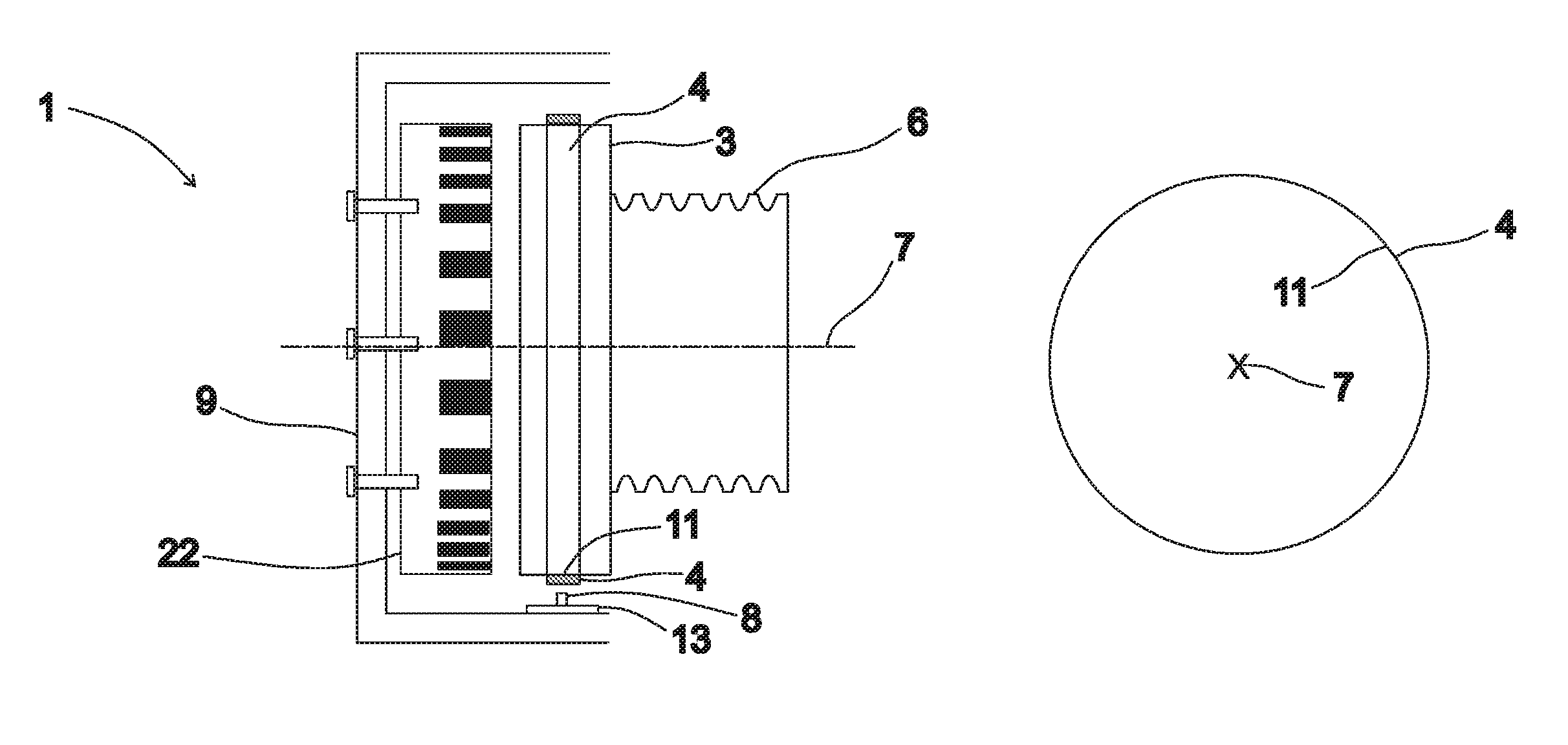
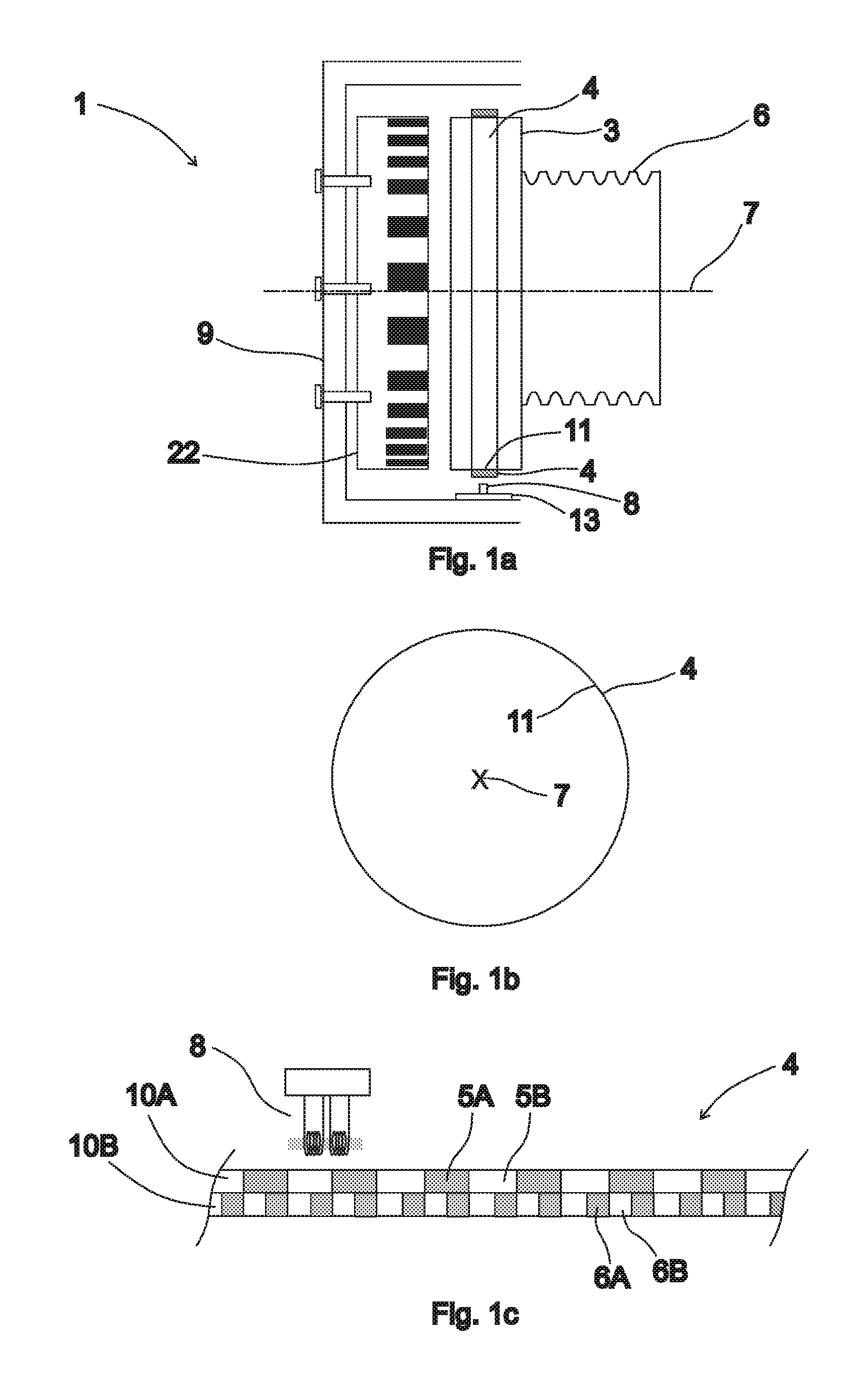
[0030]FIG. 1 a presents a side view of an elevator hoisting machine 2 with a measuring arrangement 1 according to the invention fitted in it for measuring the position and / or movement of the rotor 3 of the hoisting machine 2. FIG. 1b represents a magnetic band 4 comprised in the measuring arrangement as seen in front view. FIG. 1c presents a more detailed view of a part of a magnetic band 4 according to the invention and a reader 8 comprised in the measuring arrangement which senses the magnetic property of the magnetic band 4.

[0031]The magnetic band 4 is attached to the rotating part of the elevator hoisting machine 2, to the circumference of the rotor 3. For this purpose, the circumference of the rotor 3 is provided with a mounting surface 11 for the magnetic band 4, which mounting surface 11 forms a circle around the rotational axis 7 of the rotor and whose distance from the rotational axis 7 of the rotor is substantially constant. The magnetic band 4 is placed on the mounting su...


PUM


Abstract

A hoisting machine and an elevator system including the hoisting machine are provided. The hoisting machine includes a measuring arrangement for determining the position and / or movement of the rotor of a hoisting machine. The measuring arrangement includes a magnetic band whose magnetic property is so implemented that it varies in the longitudinal direction of the band.

Description

CROSS REFERENCE TO RELATED APPLICATIONS[0001]This application is a Continuation of PCT International Application No. PCT / FI2010 / 050741 filed on Sep. 24, 2010, which claims priority under 35 U.S.C. §119(a) to Patent Application Nos. 20095986 and 20095991 filed in Finland on Sep. 25, 2009 and Sep. 29, 2009, respectively, all of which are hereby expressly incorporated by reference into the present application.FIELD OF THE INVENTION[0002]The present invention relates to the measurement of position and / or movement and in particular to the measurement of the position and / or movement of the rotor of an electric machine.DESCRIPTION OF PRIOR ART[0003]For motor torque adjustment, it is necessary to have information regarding the position of a magnetic pole of the rotor. In addition, for the adjustment of motor movement, feedback is needed about the rotary motion of the rotor.[0004]The position of a magnetic pole of the rotor has traditionally been detected by means of an absolute sensor measu...

Claims


Application Information

Patent Timeline
Patent Type & Authority Patents(United States)
IPC IPC(8): B66B1/34
CPCB66B1/30H02K11/0021B66B1/304H02K7/1008B66B1/3492H02K11/215H02K29/08
Inventor KORHONEN, TUUKKATENHUNEN, ASMOLAHTEENMAKI, JUSSIHUPPUNEN, JUSSI
Owner KONE CORP
Why Eureka
Try Eureka