Device for cleaning oxidized or corroded components in the presence of a halogenous gas mixture

a technology of oxidized or corroded components and halogen gas mixture, which is applied in the direction of cleaning process and equipment, cleaning using liquids, chemistry apparatus and processes, etc., can solve the problems of significant malfunctions in cleaning process, mechanical weakening of respective components, and breakdown of the entire cleaning process

Inactive Publication Date: 2010-07-15
ANSALDO ENERGIA IP UK LTD
View PDF17 Cites 1 Cited by
  • Summary
  • Abstract
  • Description
  • Claims
  • Application Information

AI Technical Summary

Benefits of technology

[0015]One of numerous aspects of the present invention includes a device for cleaning oxidized or corroded components, especially gas turbine components which are exposed to hot gases, in the presence of a halogenous gas, with a cleaning retort which is in the shape of a boiler, into which, indirectly or directly, leads a feed line which via a flow control unit is connected to a reservoir which stores the halogenous gas, in such a way that on the one hand it is ensured that the problems which are associated with an inadequate or fluctuating cleaning gas feed into the cleaning retort are ameliorated or completely remedied. On the other hand, it is necessary to take measures which ensure that each individual component which is to be cleaned and to be introduced into the cleaning retort is exposed to a preferably direct onflow by the cleaning gas so that, as far as possible, no masking effects nor flow dead spaces can be formed within the gas flow. All the measures which are to be taken, moreover, are to be taken from the point of view of economical considerations and a cleaning of each individual component which is as careful as possible, but effective.
[0017]The exemplary device is based on the knowledge that condensations, which especially occur in the region of throttling points, are formed along the feed line for feed of the halogenous gas. Such condensations lead to erroneous values within the scope of gas volume controlling and can lead right up to the total failure of the volume measuring. The halogenous gas is preferably stored in pressurized bottles. Under storage conditions it is in liquid form. By increasing the temperature the liquid is evaporated and the temperature-dependent vapor pressure of the substance is established. Therefore, overpressure conditions prevail upstream of the gas control unit. The pressure inside the cleaning retort lies typically at the pressure level of 50 torr to 780 torr. Therefore, at least one pressure reducing throttling stage is required along the feed line. With this, the previous condensation problem occurs. As a throttling point along the feed line, an exemplary device includes at least one flow control unit which provides a gas volume control valve which expands the gas. For countering the condensation which is formed in this case, a heating unit, which preferably has a gas heater, is provided in the flow direction, directly following the gas volume control valve, as a result of which the temperature level in this region of the line is raised above the condensation level of the halogenous gas, preferably of HF gas. The gas volume control unit is connected directly to the heat exchanger downstream along the feed line, by which the formation of HF condensate can be efficiently avoided. Erroneous measurements, as well as a complete failure of the flow control unit, can be completely excluded with this, as a result of which, moreover, the service life of the individual components of the flow control unit is also significantly increased. This in turn has a positive effect on the initial costs and operating costs and furthermore improves the availability of such cleaning plants.

Problems solved by technology

Turbine components for power plants or stationary gas turbine installations, which are indirectly or directly exposed to hot gas flows, such as stator blades or rotor blades, heat accumulating segments or similar components or component groups which delimit the hot gas passage, are subjected to operation-induced material degradations which frequently lead to cracks and to mechanical weakening of the respective components which is associated with them.
In the longstanding association with a cleaning retort which relates to this, which via a central pipe is fed with a cleaning gas mixture which contains hydrogen fluoride and hydrogen in varying ratios, it has been shown that significant malfunctions in the cleaning process are created as a result of volume fluctuations in the feed of the cleaning gas into the cleaning retort, which, upon exceeding certain proportions, can occasionally lead to the breakdown of the entire cleaning process.
More accurate investigations furthermore showed that the feeding of fluctuating hydrogen fluoride gas volumes inside the cleaning retort lead to concentration fluctuations which ultimately result in a reduced cleaning efficiency and in an inaccurately controllable cleaning quality which is associated with it.
In particular, in the case of very badly damaged components with a large number of material cracks which furthermore have a wide spectrum with regard to depth, width, and length of the individual cracks, an intended level of cleaning under these circumstances can no longer be ensured.
A further disadvantageous and therefore improvement-deficient aspect in the case of the cleaning practices which have been used up to now relates to the construction of the cleaning retort.
On account of such a known construction, the stacking or positioning possibilities for the individual components which are to be cleaned in the cleaning retort are limited.
The equally improvement-deficient ratios of flow onto the individual components which are to be cleaned inside the cleaning retort add to this, particularly as it cannot be ruled out that, on account of a mutual masking of specific surface regions on the components which are to be cleaned, only an inadequate impingement with cleaning gas is carried out.
For countering the previously pointed out problems with regard to the improvement of cleaning quality, attempts have been made to increase the cleaning cycle times in order to maintain a longer interaction period between the components which are to be cleaned and the cleaning gas mixture, produced only inconsequential results.
However, these attempts only showed that the set cleaning aims were not focused to a satisfactory degree.
Rather, these measures led to a cost increase and also to an increased material attack on the components which are to be cleaned.
Such condensations lead to erroneous values within the scope of gas volume controlling and can lead right up to the total failure of the volume measuring.
With this, the previous condensation problem occurs.
Despite the large number of possible design variants for a respective distribution structure, it can still happen in the case of individual components which are to be cleaned that these are not optimally exposed to impingement by the cleaning gas.

Method used


Image

  • Device for cleaning oxidized or corroded components in the presence of a halogenous gas mixture
  • Device for cleaning oxidized or corroded components in the presence of a halogenous gas mixture
  • Device for cleaning oxidized or corroded components in the presence of a halogenous gas mixture

Examples


Embodiment Construction

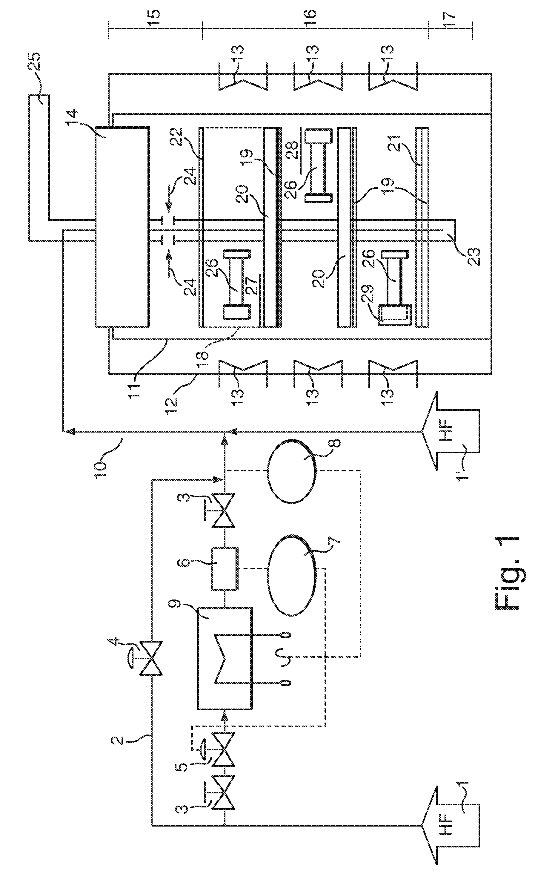
[0042]FIG. 1 illustrates a schematic construction of a cleaning retort (right-hand half of figure), which is supplied with a cleaning gas mixture via a cleaning gas piping system (left-hand half of figure). The cleaning retort has a retort housing 11 which is designed essentially in the shape of a cylinder or barrel and which on its upper side is closed off in a gastight manner with a retort cover 14. The retort housing 11 is enclosed by a heating jacket 12 in which heating devices 13 ensure a cleaning process temperature in the interior of the cleaning retort of up to 1200° C. A central pipe 23 is provided centrally inside the cleaning retort and outwardly penetrates the retort cover 14 in a gastight manner, and into which cleaning gas is fed via a feed line 10. Moreover, a retort outlet 24 is provided inside the cleaning retort, via which used cleaning gas is carried out via a corresponding exhaust gas pipe 25 for further supply or disposal.

[0043]For the provision of cleaning gas,...


PUM

PropertyMeasurementUnit
temperaturesaaaaaaaaaa
pressureaaaaaaaaaa
temperatureaaaaaaaaaa

Abstract

A device for cleaning oxidized or corroded components (26), especially gas turbine components which are exposed to hot gases, in the presence of a halogenous gas, includes a cleaning retort which is designed in the shape of a boiler or cylinder and into which, indirectly or directly, leads a feed line which is connected via a flow control unit to a gas reservoir which stores the halogenous gas, and in which a device for gas distribution is integrated. The flow control unit has a gas volume control valve (5), a heat exchanger unit (9), and also a gas volume measuring unit (6) in sequence along the throughflow direction of the halogenous gas which flows through the feed line. Furthermore, a gas distribution in the retort directs the halogenous gas directly to the components which are to be cleaned.

Description

BACKGROUND[0001]1. Field of Endeavor[0002]The invention relates to a device for cleaning oxidized or corroded components in the presence of a halogenous gas mixture, with a cleaning retort into which, indirectly or directly, leads a feed line which is connected via a flow control unit to a gas reservoir which stores the halogenous gas mixture. In particular, these components can be turbine components, especially gas turbine blades, which are exposed to impingement by hot gases.[0003]2. Brief Description of the Related Art[0004]Turbine components for power plants or stationary gas turbine installations, which are indirectly or directly exposed to hot gas flows, such as stator blades or rotor blades, heat accumulating segments or similar components or component groups which delimit the hot gas passage, are subjected to operation-induced material degradations which frequently lead to cracks and to mechanical weakening of the respective components which is associated with them. On accou...

Claims


Application Information

Patent Timeline
Patent Type & Authority Applications(United States)
IPC IPC(8): B08B5/00
CPCC23G5/00F05D2230/11F01D5/005
Inventor LUTTERMAN, ANSGARSTANKOWSKI, ALEXANDERBINDERNAGEL, KARSTEN
Owner ANSALDO ENERGIA IP UK LTD
Why Eureka
Try Eureka