Humidifier

a technology of humidifier and humidifier body, which is applied in the field of new humidifiers, can solve the problems of hidden dangers to human skin and health, electrocution and personal injury, and achieve the effects of effective separation of liquid and electricity, extending the service life of the control circuit assembly, and improving the overall safety index

Active Publication Date: 2022-03-22
ZHONGSHAN STYLE ELECTRIC APPLIANCES TECH CO LTD
View PDF11 Cites 0 Cited by
  • Summary
  • Abstract
  • Description
  • Claims
  • Application Information

AI Technical Summary

Benefits of technology

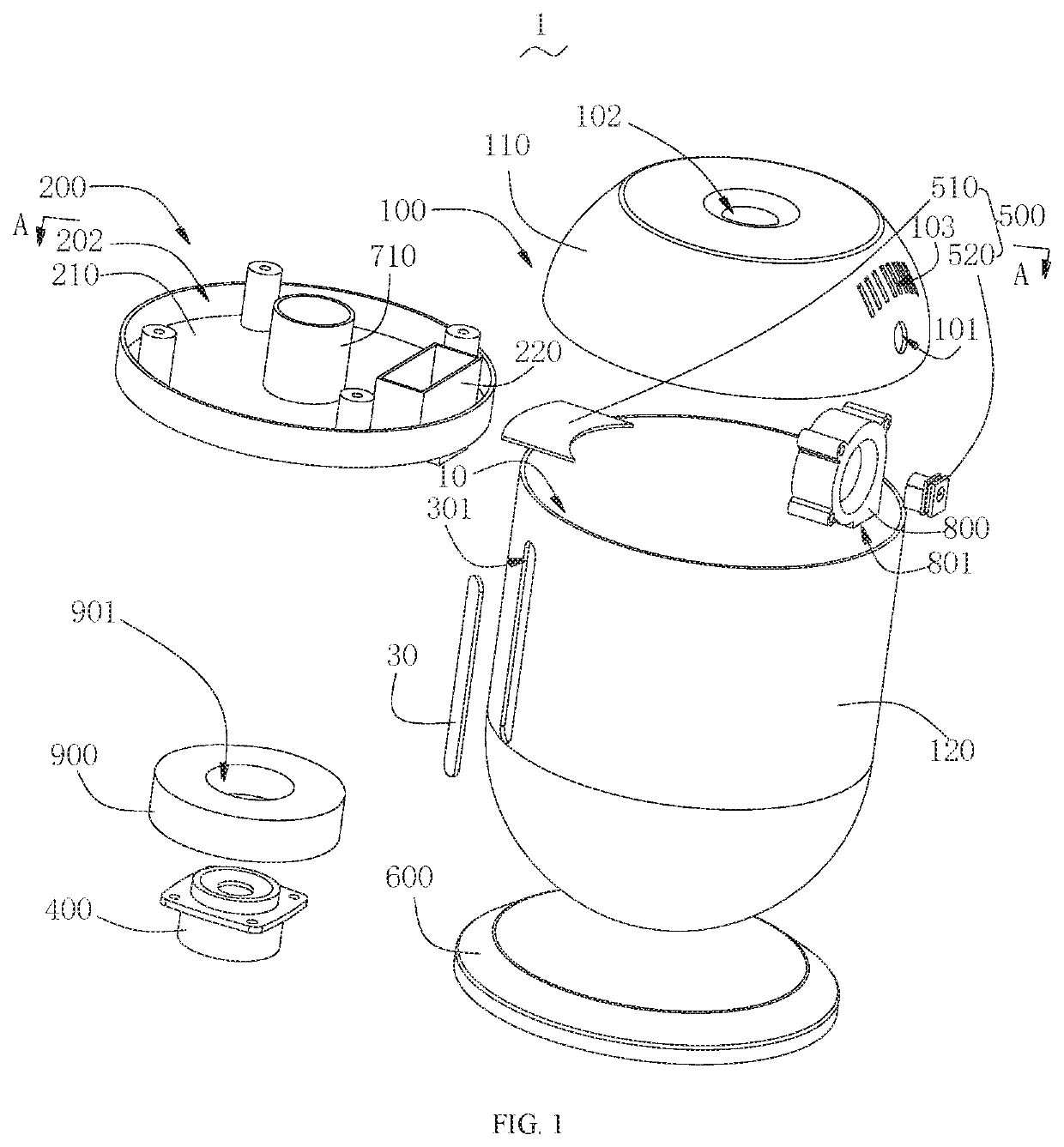
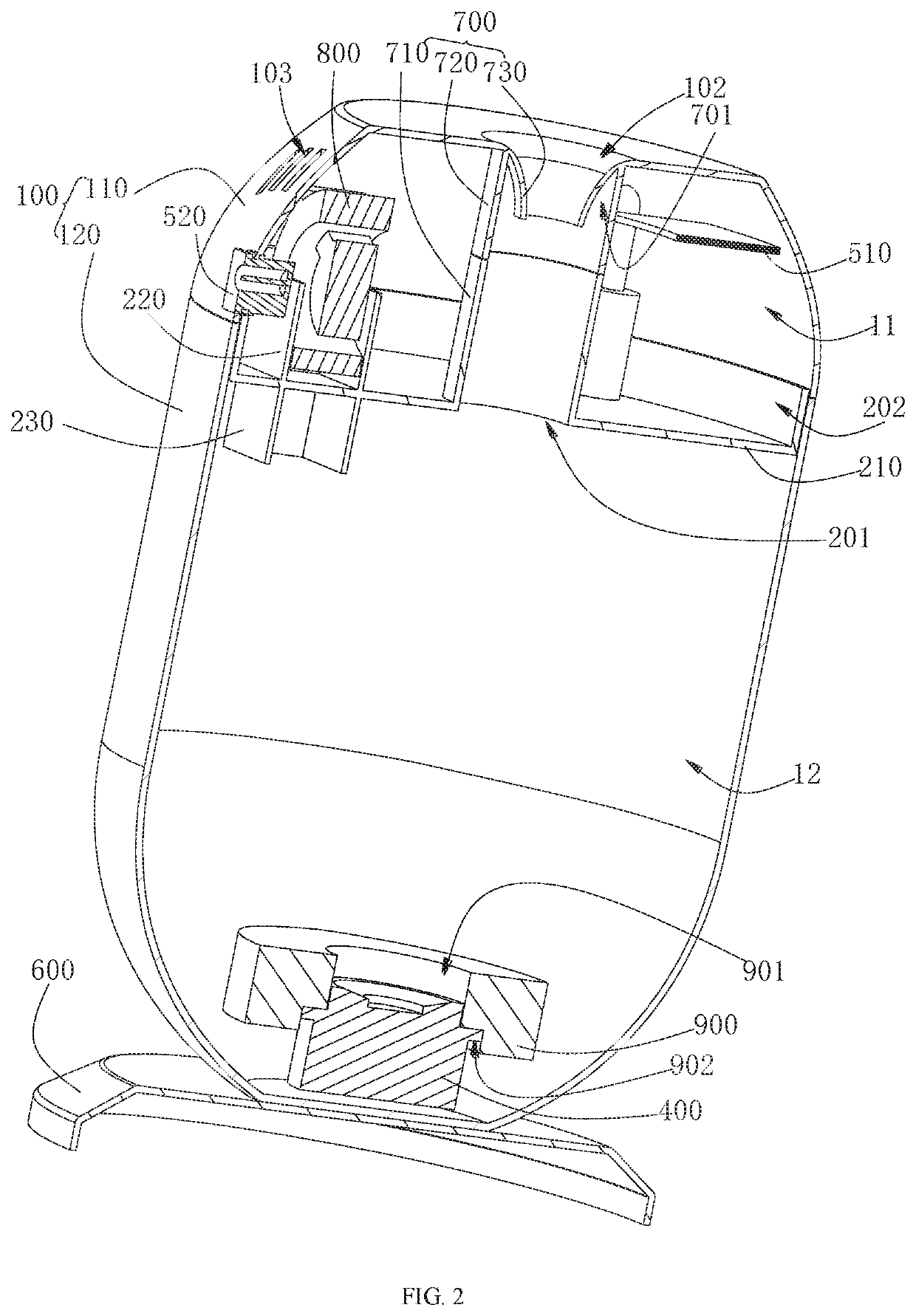
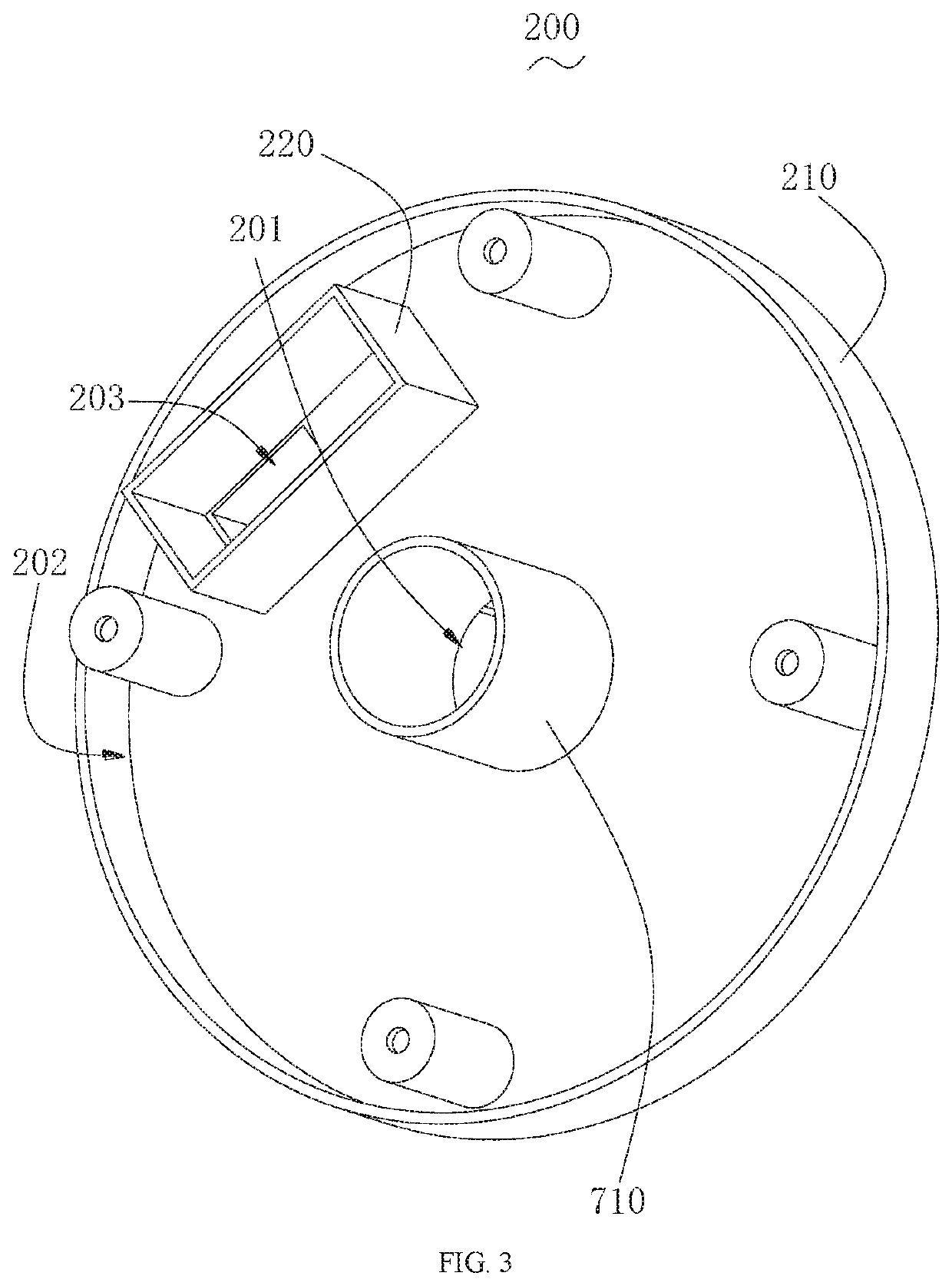
[0020]A beneficial effect of the present disclosure: the shell has a containing cavity, the fixing bracket is disposed in the containing cavity, and the fixing bracket divides the containing cavity into a first isolating cavity and a second isolating cavity which are opposite, the control circuit assembly is disposed in the first isolating cavity, a solution is contained in the second isolating cavity, a atomizer is positioned in the solution in the second isolating cavity and electrically connected to the control circuit assembly, and the control circuit assembly controls the atomizer so that the atomizer atomizes the solution in the second isolating cavity. Thus by the arrangement of the fixing; bracket, the containing cavity is divided into a first isolating cavity for installing the control circuit assembly and a second isolating cavity for storing the solution, thereby effectively separating the liquid and electricity, and preventing direct contact between the control circuit assembly and the solution, improving the overall safety index and extending, service life of the control circuit assembly.

Problems solved by technology

Autumn and winter seasons are the driest seasons of the year, especially in the north, where the air is very thy, which brings some hidden dangers to human skin and health.
Currently, water tanks of conventional humidifiers circulating on the market are mostly placed on a top portion of the humidifiers, and the circuit components are in direct contact with water, which may cause electrocution and personal injury.

Method used


Image

  • Humidifier
  • Humidifier
  • Humidifier

Examples


Embodiment Construction

[0026]To make the objects, technical solutions and advantages of the present disclosure more comprehensible, the present disclosure will be further described in detail below regarding the accompanying drawings and embodiments. It should be understood that the specific embodiments described herein are merely illustrative of the disclosure and are not intended to limit the disclosure.

[0027]It should be noted that when an element is referred to as being “fixed” or “disposed” on another element, it can be directly fixed or disposed on the other element or it can be indirectly fixed or disposed on the other element through a third component. When an element is referred to as being “connected” to another element, it can be directly connected to the other element or it can be indirectly connected to the other element through a third component.

[0028]It is to be understood that the terms “length, width, upper, lower, front, rear, left, right, vertical, horizontal, top, bottom, inner, outer”,...


PUM


Abstract

A humidifier includes a shell, a fixing bracket, an atomizer, and a control circuit assembly, and the fixing bracket is disposed in a containing cavity of the shell and divides the containing cavity into a first isolating cavity and a second isolating cavity opposite to each other; the control circuit assembly is disposed in the first isolating cavity, and a solution is contained in the second isolating cavity; the atomizer is positioned in the solution of the second isolating cavity and electrically connected to the control circuit assembly. The control circuit assembly controls the atomizer to atomize the solution.

Description

CROSS-REFERENCE TO RELATED APPLICATIONS[0001]This application claims the benefit of Chinese patent application No. 201921108697.9 filed on Jul. 16, 2019, and PCT patent application PCT / CN20191100913 filed on Aug. 16, 2019. All the above are hereby incorporated by reference in their entirety.BACKGROUNDTechnical Field[0002]The present disclosure relates to the technical field of humidifiers, and particularly relates to a new humidifier.Background Art[0003]With the development of society and the improvement of living standards, the quality of people's life has been continuously improved, and people's awareness of their health have also changed greatly. Autumn and winter seasons are the driest seasons of the year, especially in the north, where the air is very thy, which brings some hidden dangers to human skin and health. Hence, a humidifier becomes an indispensable household appliance, which can increase the humidity of the air and keeps the skin moisturized. Therefore, various humidi...

Claims


Application Information

Patent Timeline
Patent Type & Authority Patents(United States)
IPC IPC(8): F24F6/02F24F6/00
CPCF24F6/025F24F2006/008F24F6/06
Inventor LIU, TAOWAN, BAOPINGZHANG, LIPINGHU, LIMINQIN, XIAOPENG
Owner ZHONGSHAN STYLE ELECTRIC APPLIANCES TECH CO LTD
Why Eureka
Try Eureka