Protective device

a protective device and battery technology, applied in the direction of emergency protective circuit arrangement, circuit arrangement, electric equipment, etc., can solve the problems of explosion of batteries of portable electronic products, and achieve the effect of effective prevention of overcurrent and overvoltag

Active Publication Date: 2013-06-25
CYNTEC
View PDF39 Cites 5 Cited by
  • Summary
  • Abstract
  • Description
  • Claims
  • Application Information

AI Technical Summary

Benefits of technology

[0007]An object of the present invention is to provide a protective device for effectively preventing over-current and over-voltage.
[0008]In one aspect, the present invention provides a protective device for a electrical circuit, comprising a substrate supporting a conductive section that includes a metal element electrically connected between first and second electrodes, wherein the metal element serves as a sacrificial structure having a melting point lower than that of the first and second electrodes, and a first auxiliary medium disposed between the metal element and the substrate, wherein the first auxiliary medium having a melting point lower than that of the metal element, and wherein the first auxiliary medium facilitates breaking of the metal element upon melting to protect the electric circuit from over voltage and / or current. The protective device may be provided with a heat-generating element supported by the substrate, providing heat to at least the auxiliary medium. The heat-generating element may be supported between the metal element and the substrate or supported by a side of the substrate away from the heating element.
[0009]In another aspect of the present invention, the protective device further comprises an intermediate support (e.g., another electrode) disposed between the metal element and the substrate, wherein the auxiliary medium are disposed on either side of the intermediate support. The intermediate support further facilitates breaking of the metal element upon melting to protect the electric circuit. The intermediate support is heated by the heat generating element, if provided.
[0010]In another aspect of the present invention, the protective device further comprises a first intermediate layer (e.g., a solder layer) between the metal element and the intermediate support, wherein the intermediate layer has a first fusing temperature lower than the melting temperature of the metal element. The first intermediate layer fuses with the metal element to further facilitate breaking of the metal structure upon melting to protect the electric circuit. Further second intermediate layer (e.g., another solder layer) having a lower fusing temperature may be provided between the metal element and the first and second electrodes.
[0012]In yet another aspect of the present invention, at least the first electrode comprises a protrusion extending towards the metal element, wherein the protrusion provides additional contact for melted metal element to facilitate breaking of the metal element to protect the circuit.
[0018]In light of the above, the auxiliary medium is embedded in the protective device of the present invention, and the auxiliary medium is disposed between the metal element and the heat-generating element. Therefore, when the heat-generating element generates heat, the auxiliary medium effectively helps melt the metal element. Furthermore, at least one of the first electrode and the second electrode of the protective device has a protrusion. Hence, when the heat-generating element generates heat, the auxiliary medium which is heated effectively facilitates melting of the metal element, and the melted metal element flows towards the protrusion due to surface tension, meaning that the protrusion increase flowing space and adhesive area of the melted metal element, thereby preventing short-circuiting caused by the melted metal element electrically connecting the extending portions and the electrodes. In addition, the protective device of the present invention has a low thermal conductive layer, and when the heat-generating element generates heat, heat can be transferred to the third electrode concentratively via the substrate. Therefore, the metal element located over the third electrode will be blown firstly to reduce the melt value of the metal element, and over voltage protection or an over current protection is achieved.

Problems solved by technology

However, lately there has been news about exploding batteries of portable electronic products during charging and discharging.

Method used


Image

  • Protective device
  • Protective device
  • Protective device

Examples


Embodiment Construction

[0035]Reference will now be made in detail to the present preferred embodiments of the invention, examples of which are illustrated in the accompanying drawings. Wherever possible, the same reference numbers are used in the drawings and the description to refer to the same or like parts.

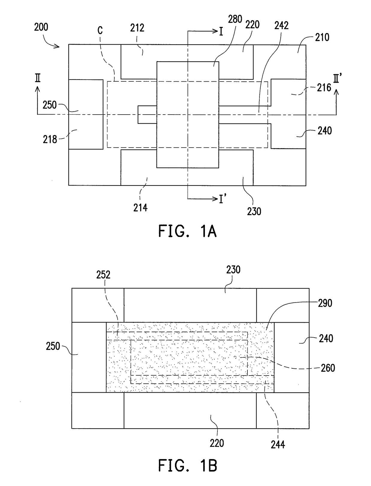
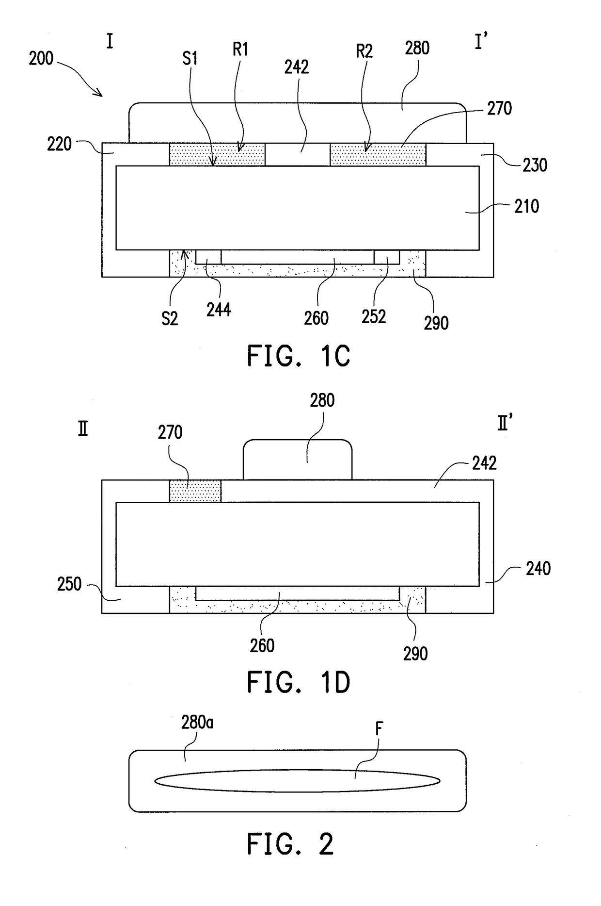
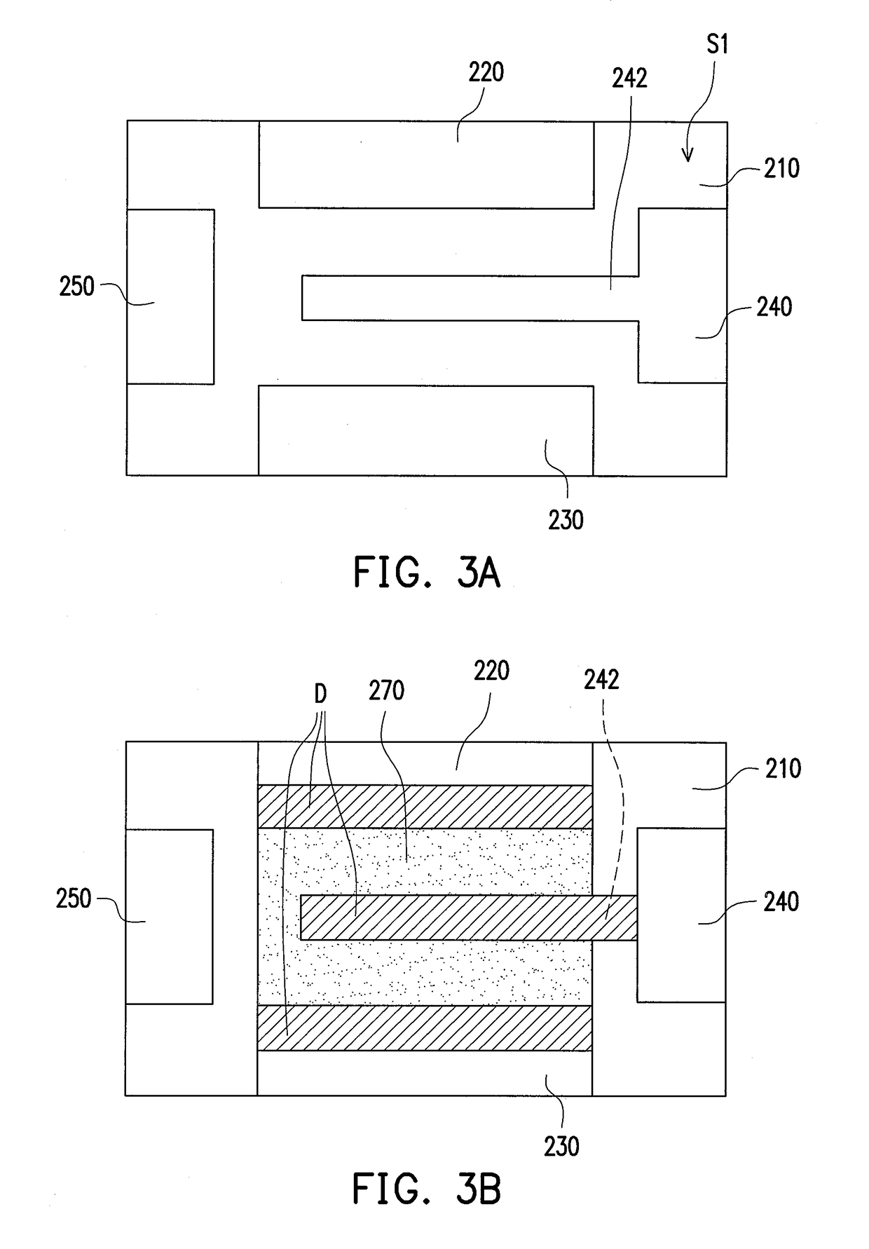
[0036]Referring to FIGS. 1A, 1B, 1C, and 1D, according to one embodiment of the present invention, a protective device is provided. The protective device 200 of the present embodiment includes a substrate 210, a first electrode 220, a second electrode 230, a third electrode 240, a fourth electrode 250, a heat-generating element 260, an auxiliary medium 270, and a conductive section. The first electrode 220, the second electrode 230, the third electrode 240, and the fourth electrode 250 are respectively disposed on the substrate 210. Herein, the conductive section is supported by the substrate 210 and includes a metal element 280 electrically connected between the first electrode 210 and the second el...


PUM

PropertyMeasurementUnit
distanceaaaaaaaaaa
thermal conductivity coefficientaaaaaaaaaa

Abstract

A protective device including a substrate, a conductive section and a first auxiliary medium is provided. The conductive section is supported by the substrate, wherein the conductive section comprises a metal element electrically connected between first and second electrodes. The metal element serves as a sacrificial structure having a melting point lower than that of the first and second electrodes. The first auxiliary medium is disposed between the metal element and the substrate, wherein the first auxiliary medium has a melting point lower than that of the metal element. The first auxiliary medium facilitates breaking of the metal element upon melting.

Description

CROSS-REFERENCE TO RELATED APPLICATION[0001]This application claims the priority benefit of Taiwan application serial no. 98129872, filed on Sep. 4, 2009, Taiwan application serial no. 99115506, filed on May 14, 2010 and Taiwan application serial no. 98129874, filed on Sep. 4, 2009. The entirety of each of the above-mentioned patent applications is hereby incorporated by reference herein and made a part of this specification.BACKGROUND OF THE INVENTION[0002]1. Field of the Invention[0003]The present invention relates to a protective device applied to an electronic device, and more particularly to a protective device which prevents over currents and over voltages.[0004]2. Description of Related Art[0005]In recent years, due to the boom in information technologies (IT), IT products such as cell phones, computers and personal digital assistants are commonplace. With their help, demands in various aspects such as food, clothing, housing, travelling, education, and entertainment are met,...

Claims


Application Information

Patent Timeline
Patent Type & Authority Patents(United States)
IPC IPC(8): H02H5/00
CPCH01H85/0411H01H85/0047H02H5/00H01H69/022H01H85/0065H01H85/046H01H2085/466H01H85/048H01H85/11
Inventor WANG, CHUNG-HSIUNGLIN, HUNG-MINGCHIANG, LANG-YILUO, WEN-SHIANGCHEN, KUO-SHU
Owner CYNTEC
Why Eureka
Try Eureka