Electronic lock

Inactive Publication Date: 2008-04-01
KUO CHING HUNG
View PDF10 Cites 29 Cited by
  • Summary
  • Abstract
  • Description
  • Claims
  • Application Information

AI Technical Summary

Benefits of technology

[0018]After unlocking, a front end of the second bolt protrudes out from the housing, whereupon the protruding base of the second bolt is used to press the steel ball, thereby enabling the

Problems solved by technology

Hence, shortcomings common in such types of locksets of prior art include the inability to reduce size, a relatively complicated internal mechanism, high cost of manufacture, the inconvenience of repair after damage, and so on.
However, the freely retractable movement of the aforementioned s

Method used


Image

  • Electronic lock
  • Electronic lock
  • Electronic lock

Examples


Example

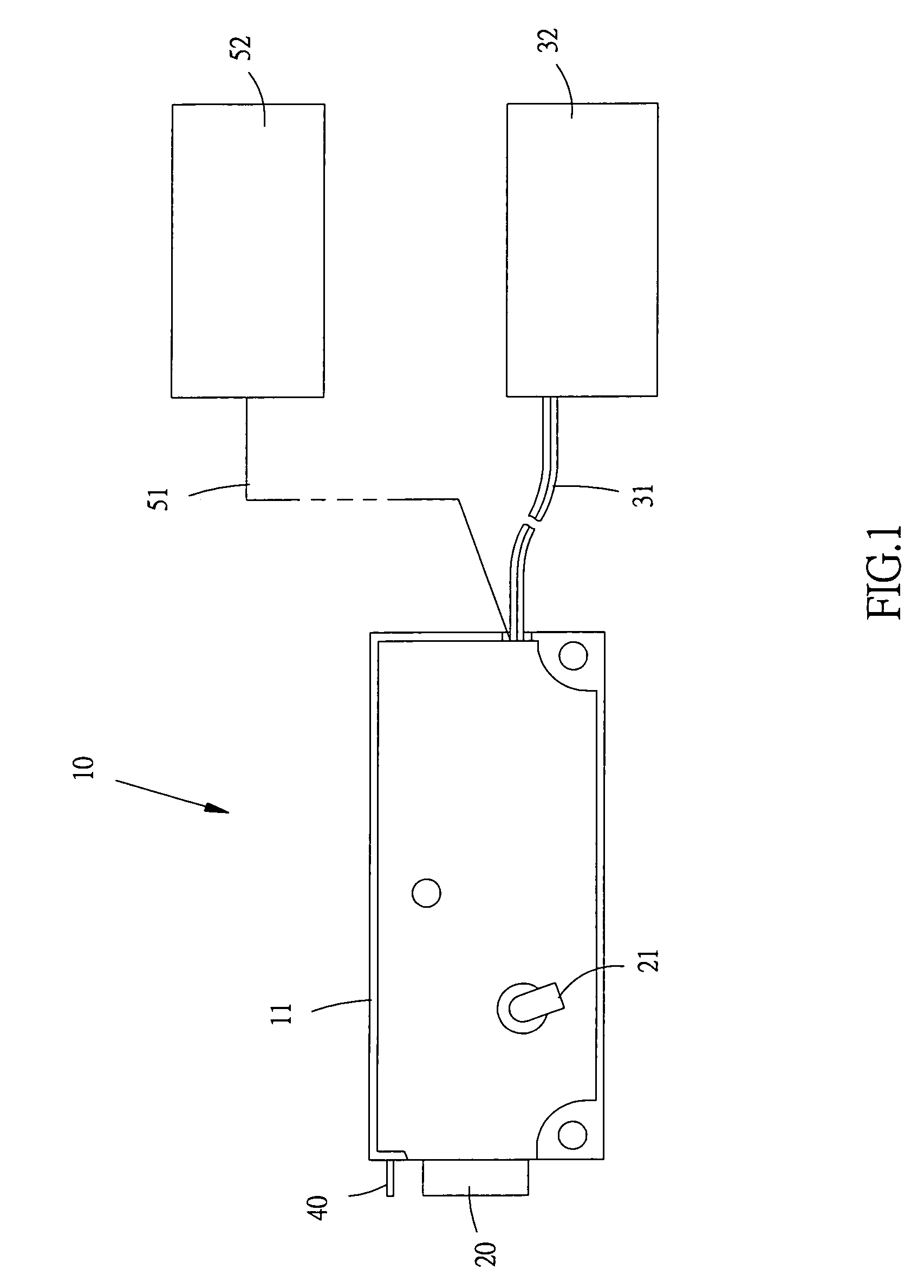
[0027]Referring to FIG. 1, which shows a schematic view of an electronic lock 10 of the present invention connected to an input device 32 and an external security system 52.

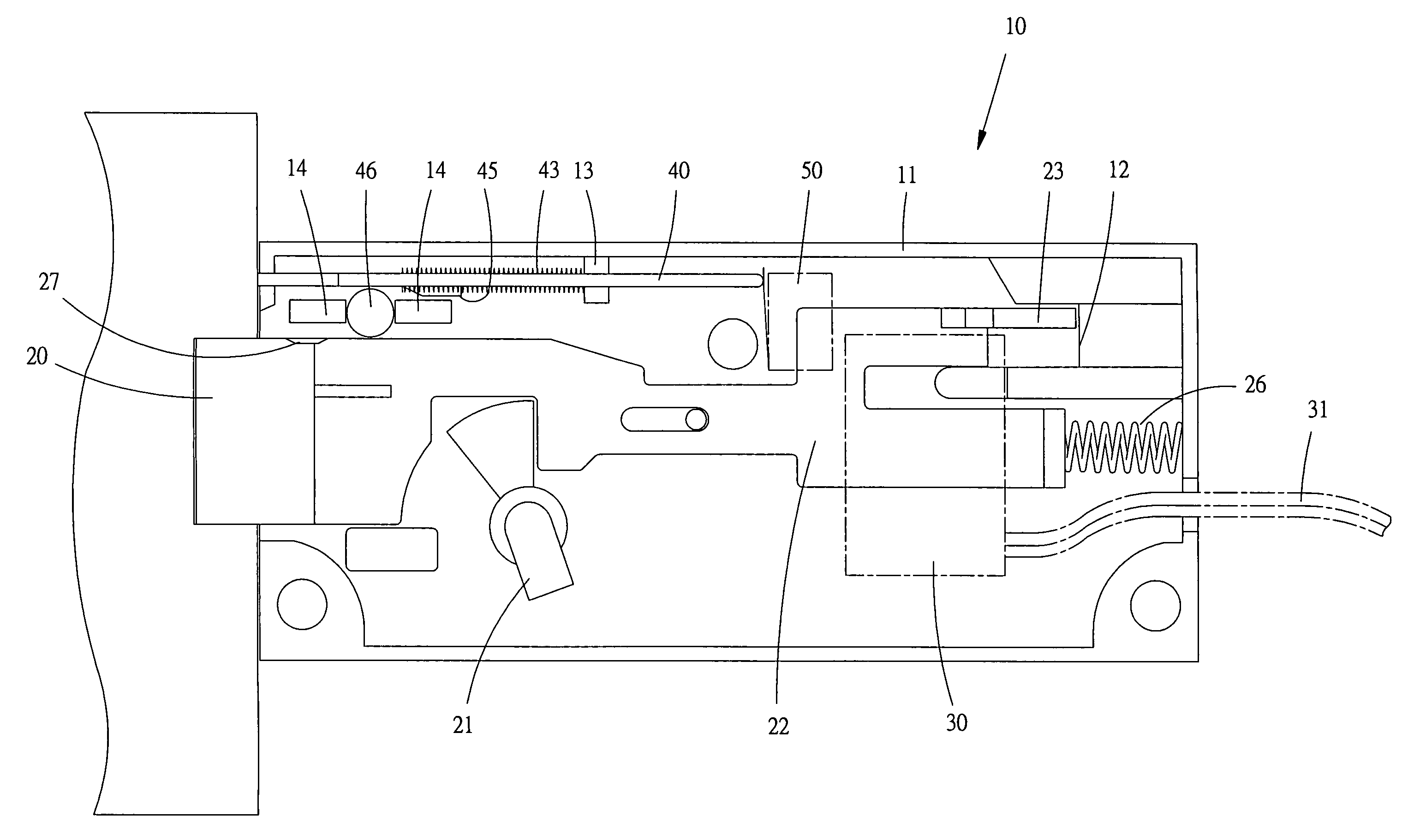
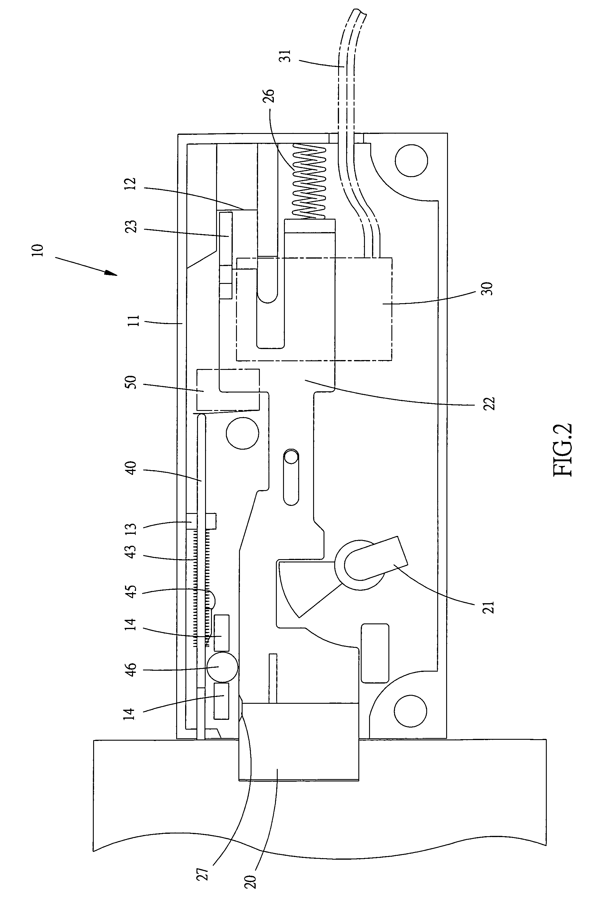
[0028]Referring to FIG. 2, which shows a planar view of internal component members of the electronic lock 10 of the present invention depicting the electronic lock 10 in a locked state, wherein a protruding first bolt 20 is already clamped within a lockhole, and a second bolt 40 is retracted within the interior of a housing 11, at which time an end of the second bolt 40 triggers a microswitch 50 to activate the security system 52.

[0029]Referring to FIG. 1 and FIG. 2, which show the electronic lock 10 of the present invention structured to comprise the first bolt 20 configured with an elastic clasp 23, an electromagnetic device 30 connected to the input device 32, the second bolt 40 and the microswitch 50 connected to the security system 52, all of which are installed interior of the housing 11 of the electronic l...


PUM


Abstract

The present invention provides an electronic lock structured to include a first bolt configured with an elastic clasp, an electromagnetic device connected to an input device, a second bolt and a microswitch connected to a security system, all of which are installed interior of a housing of the electronic lock. The elastic clasp is retained by a protruding edge of the housing, thereby disenabling the first bolt from an arbitrary retracting movement that would otherwise render the lock incapable of being unlocked. The input device controls the electromagnetic device to induce the elastic clasp and release a retaining state, and then directly rotating a rotating button causes a retracting movement of the first bolt and unlocking of the electronic lock, which simultaneously disconnects the security system. After unlocking, a front end of the second bolt protrudes out from the housing, whereupon a protruding base of the second bolt is used to press a steel ball, thereby enabling the second bolt to form a substantially stable position, which ensures effective prevention of mistaken locking and avoids forgetting to lock. Moreover, when in a locked state, the second bolt retracts within the housing and triggers the microswitch to activate the security system, thereby providing the present invention with security and convenience of operation.

Description

BACKGROUND OF THE INVENTION[0001](a) Field of the Invention[0002]The present invention relates to an electronic lock, and more particularly to an electronic lock structured to include an input device that controls an electromagnetic device to release a retaining state and enable unlocking by functioning in coordination with a rotating button. Moreover, after unlocking, a second bolt is used to form a stable fixed position, which ensures effective prevention of mistaken locking and avoids forgetting to lock. Furthermore, a microswitch is triggered to activate a security system when the second bolt is retracted, thereby providing a secure electronic lock that is convenient to operate.[0003](b) Description of the Prior Art[0004]In order to achieve the objectives of preventing illegal opening, while at the same time being provided with confidentiality and convenience of opening, locksets used in conventional vaults and safes are all designed with two keys that are respectively inserted ...

Claims


Application Information

Patent Timeline
IPC IPC(8): E05B47/06
CPCE05B45/06E05B47/0607E05B63/20E05B17/2011E05B55/12E05B2063/207Y10S70/30Y10S70/06Y10T292/546Y10T70/7062Y10T70/5226Y10T70/7136Y10T70/7079Y10T70/7107Y10T292/0982Y10T292/098Y10T70/7102
Inventor KUO, CHING-HUNG
Owner KUO CHING HUNG
Why Eureka
Try Eureka