Power supply device and vehicle including power supply device

a power supply device and power supply technology, applied in the direction of batteries, cell components, jackets/cases materials, etc., can solve the problems of leakage of current, short circuit current leakage, current leakage, etc., to achieve efficient cooling, reduce air moisture content, and reduce air moisture conten

Active Publication Date: 2013-02-07
SANYO ELECTRIC CO LTD
View PDF3 Cites 28 Cited by
  • Summary
  • Abstract
  • Description
  • Claims
  • Application Information

AI Technical Summary

Benefits of technology

[0028]According to the thus-constructed power supply device, the electrically insulating film can be brought in tight contact with the surface of the exterior container. As a result, it is possible to suppress that water is condensed between the exterior container and the electrically insulating film. The reason is that air can be reduced which remains between the electrically insulating film and the exterior container so that the amount of moisture contained in the air layer can be reduced.
[0029]In a power supply device according to the present invention, a cooling plate 7 can be further provided which is thermally connected and fastened to the bottom surfaces 11B of the rectangular battery cell 1 so that the rectangular battery cells 1 can be forcedly cooled by the cooling plate 7. According to the thus-constructed power supply device, the rectangular battery cells can be watertightly covered, while the rectangular battery cells can be more efficiently cooled by the cooling plate. The reason is that the bottom surfaces of the exterior containers of the rectangular battery cells can be thermally connected through small thermal resistivity to the cooling plate.

Problems solved by technology

If water is condensed on the surface of the exterior container, the condensed water may cause leakage of current and short circuit current.
The reason is that current may flow through the condensed water from one exterior container to another exterior container adjacent to this one exterior container, or current may flow through the condensed water from the exterior container to the ground line, and cause leakage of current.
Accordingly, if the bottom surface of the exterior container comes in contact with the exterior case or the cooling plate, the problem will arise that short current flows from the rectangular battery cell, or leakage of current occurs.
Accordingly, the thermally connected state will be poor.
As a result, there is a problem that will be difficult to hold the rectangular battery cells 101 on the same plane.
On the other hand, since the welded part protrudes from the bottom surface of the rectangular battery cell, the welded part will be likely damaged by the weight of the battery block, or vibration.
As a result, in the case where the battery block is placed on and is fastened to the bottom plate of the exterior case or the cooling plate, the damage on the heat contraction sheet may cause leakage of current or short circuit.
In the thus-constructed battery block, the exterior container may not be directly thermally connected to the cooling plate, which in turn may reduce cooling effect.
In this case, since a particular part of the bottom of the exterior container is locally supported by the separator, there is a problem that this part in contact with the separator may be likely to be damaged.

Method used


Image

  • Power supply device and vehicle including power supply device
  • Power supply device and vehicle including power supply device
  • Power supply device and vehicle including power supply device

Examples


Embodiment Construction

)

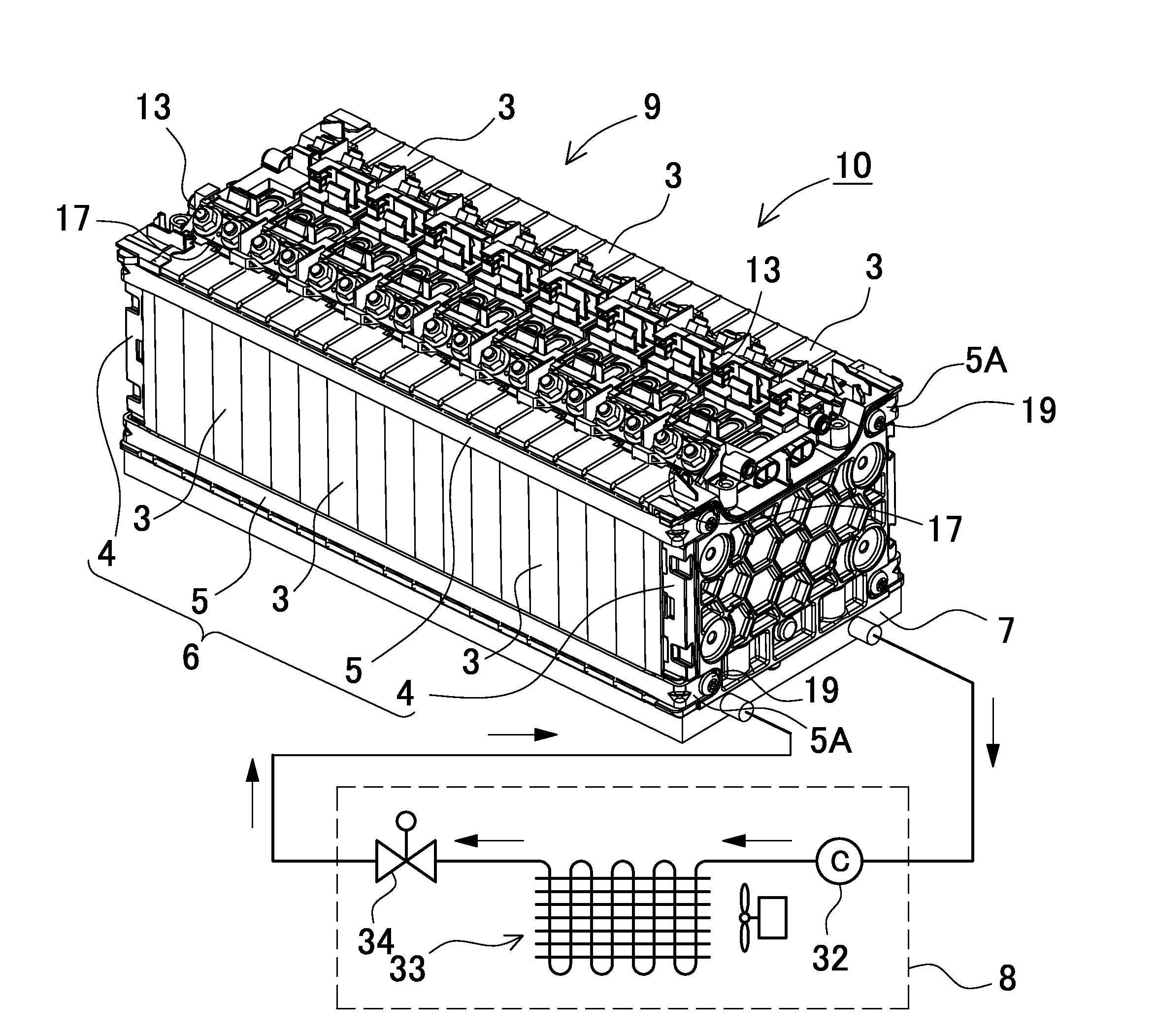
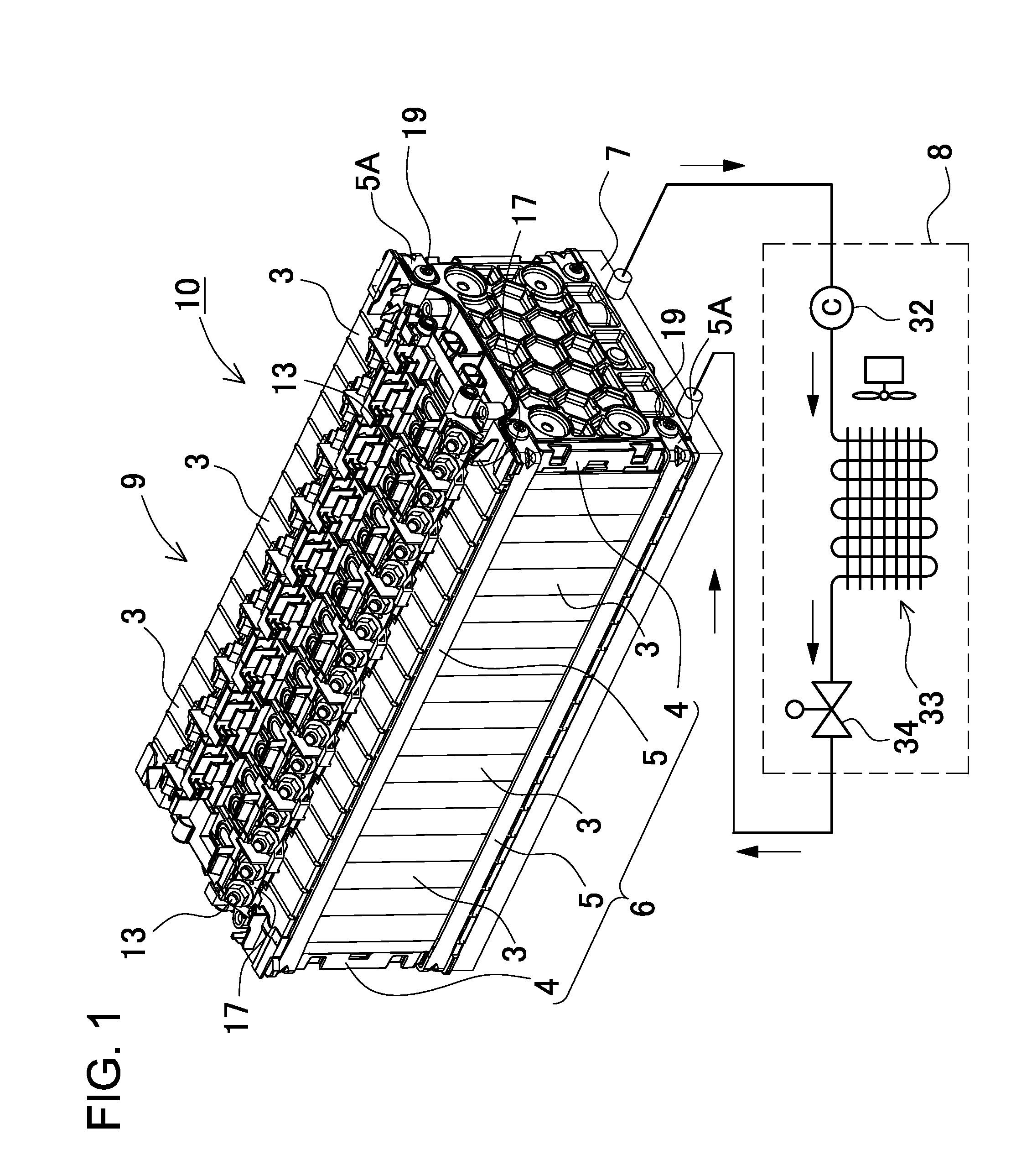
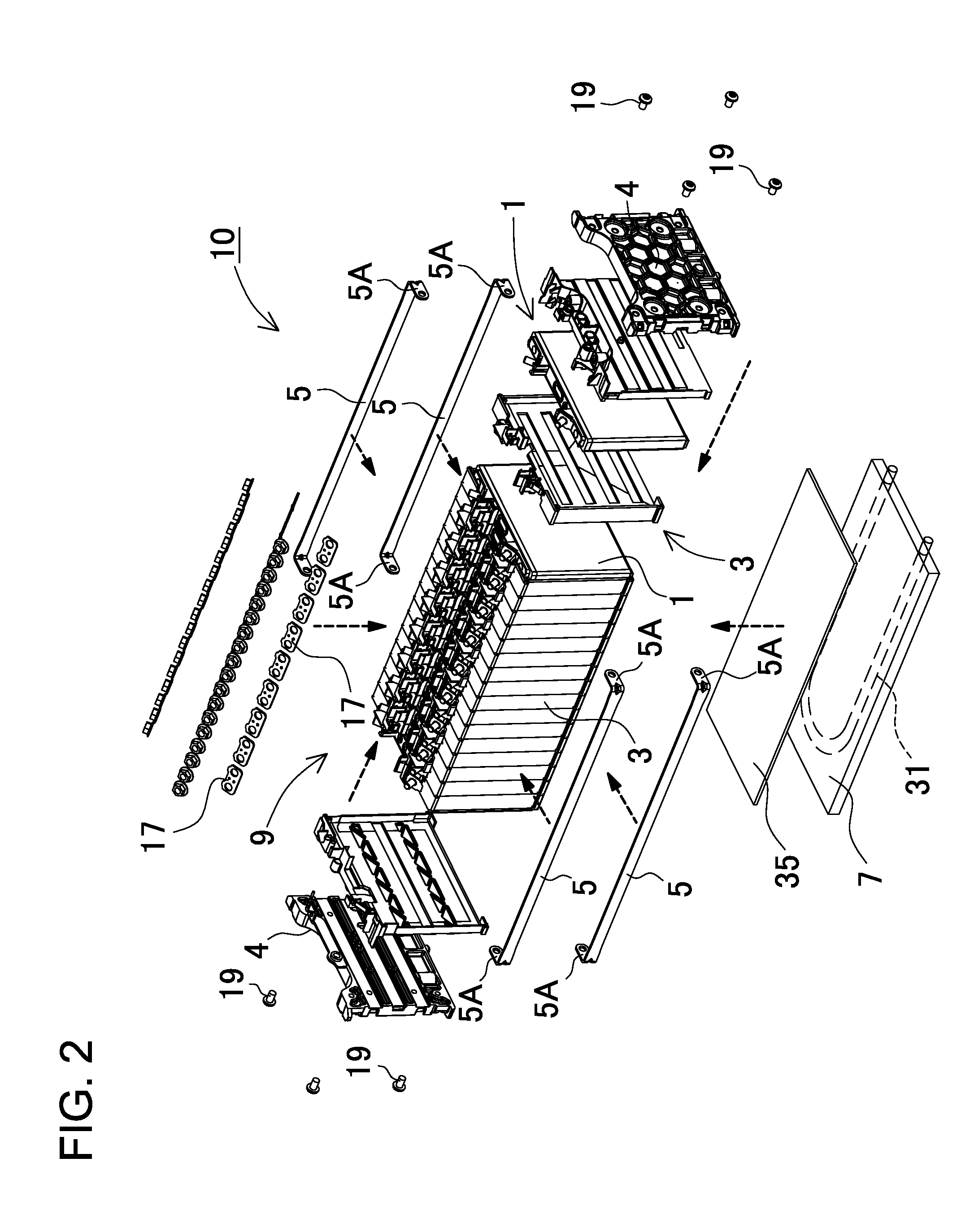
[0074]The following description will describe embodiments according to the present invention with reference to the drawings. It should be appreciated, however, that the embodiments described below are illustrations of a power supply device and a vehicle including this power supply device to give a concrete form to technical ideas of the invention, and a power supply device and a vehicle including this power supply device of the invention are not specifically limited to description below. Furthermore, it should be appreciated that the members shown in claims attached hereto are not specifically limited to members in the embodiments. Unless otherwise specified, any dimensions, materials, shapes and relative arrangements of the members described in the embodiments are given as an example and not as a limitation. Additionally, the sizes and the positional relationships of the members in each of drawings are occasionally shown larger exaggeratingly for ease of explanation. Members same ...


PUM

PropertyMeasurementUnit
angleaaaaaaaaaa
electrically insulatingaaaaaaaaaa
areasaaaaaaaaaa

Abstract

A power supply includes rectangular battery cells 1. Each cell 1 includes a rectangular container 11 covered with an electrically insulating film 2. The film 2 has a bottom cover 22, main covers 21, and side covers 23. The bottom cover 22 is arranged between the main covers 21. The side covers 23 protrude from the both sides of the main and bottom covers 21 and 22. Each side cover 23 has first and second side covers 23A and 23B. The first and second side covers 23A and 23B protrude from the side edges of the main and bottom covers 21 and 22. The first and second side covers 23A and 23B are continuously arranged in connection areas 24. When folded on side surfaces 11D of the container 11, the first and second side covers 23A and 23B are superposed on one another. The superposed parts 25 are welded.

Description

BACKGROUND OF THE INVENTION[0001]1. Field of the Invention[0002]The present invention relates to a power supply device that includes a number of battery cells, which are arranged side by side, and in particular to a power supply device that can supply electric power to an electric motor for vehicle traveling, a power supply device that can be charged with electric power generated by natural power sources such as solar batteries or with midnight electric power, a power supply device suitable as blackout backup power supplies that are suitably prepared for a blackout, and a vehicle that includes the power supply device.[0003]2. Description of the Related Art[0004]A power supply device required to provide a large amount of output power includes a number of batteries that are connected in series or in parallel to each other for increasing its output power. For example, a plurality of rectangular battery cells are arranged side by side in an exterior case (see Japanese Patent Laid-Open P...

Claims


Application Information

Patent Timeline
Patent Type & Authority Applications(United States)
IPC IPC(8): H01M2/10H01M10/50H01M10/60H01M10/613H01M10/625H01M10/627H01M10/647H01M10/6554H01M10/6563H01M10/6569H01M50/119H01M50/141
CPCH01M2/0262H01M2/0267H01M2/0277H01M2/1094H01M2220/20H01M10/5016H01M10/5032H01M10/5057H01M10/5075H01M10/5004H01M10/625H01M10/647H01M10/6556H01M10/6567H01M10/613Y02E60/10H01M50/24H01M50/141H01M50/119
Inventor OCHI, SHINGOKUME, MASAO
Owner SANYO ELECTRIC CO LTD
Why Eureka
Try Eureka