Disc shaped regulated drip irrigation emitter

a technology of drip irrigation and emitters, which is applied in watering devices, horticulture, agriculture, etc., can solve the problems of increasing the difficulty of rolling and packaging conduits, changing drip rate, and increasing the cost of elastomer materials, so as to minimize the cost and size of the pressure regulating diaphragm, and the effect of small size and thickness

Active Publication Date: 2013-08-20
RIVULIS PLASTRO LTD
View PDF41 Cites 41 Cited by
  • Summary
  • Abstract
  • Description
  • Claims
  • Application Information

AI Technical Summary

Benefits of technology

[0009]The drip irrigation emitter is disc shaped and has a first face bonded to a water conduit wall, a second face having an opening exposed to the water pressure in the conduit, and a plurality of filtering slots in a side surface between the first face and the second face. A labyrinth connects between the filtering slots and an outlet hole. A pressure or flow regulating diaphragm in the emitter flexes in response to water pressure fluctuations in the conduit, providing for a substantially constant flow rate from the emitter.
[0010]The sides of the drip irrigation emitter provide a large filtering area to provide a sufficient volume of water flowing into the emitter, despite the emitter's small size. The emitter's small size and thickness make it sufficiently low in cost for single use applications, make it useful when packaging and shipping thin walled water conduits such as drip tape, and minimize the cost and size of the pressure regulating diaphragm.

Problems solved by technology

Changes in drip rate are a problem because some areas may receive too much or too little water, and it is desirable to have a relatively uniform drip rate along the length of the water conduit.
However, each emitter has a thickness that may cause a bulge or lump that increases the difficulty of rolling and packaging the conduit, especially with thin walled drip tape, e.g., 15 mil or less.
The elastomer material may be rather costly, and attempts to replace the elastomeric element with other less costly materials have not been successful because other materials are not sufficiently flexible over time due to compression set of the material, and as a result may decrease the flow rate to an unacceptable rate.
However, it is increasingly difficult to provide a large filtering area if the emitter is reduced in size.

Method used


Image

  • Disc shaped regulated drip irrigation emitter
  • Disc shaped regulated drip irrigation emitter
  • Disc shaped regulated drip irrigation emitter

Examples


Embodiment Construction

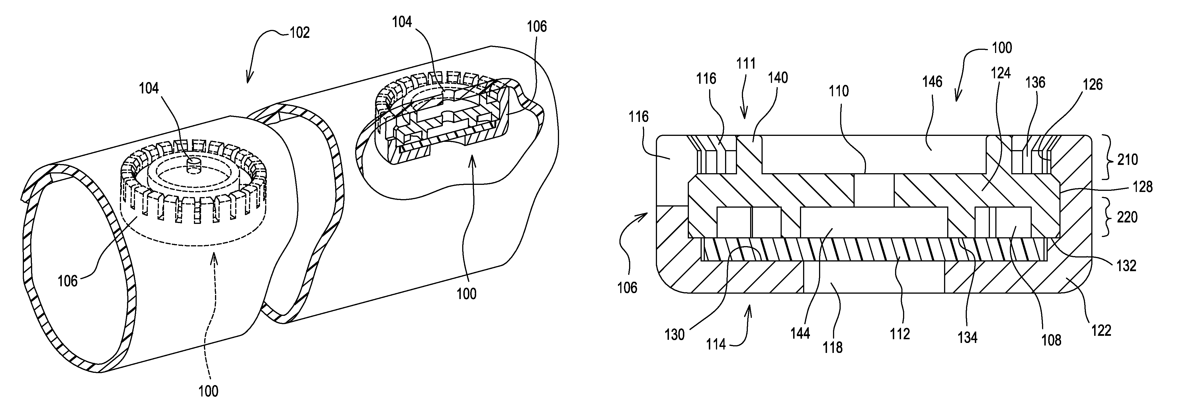
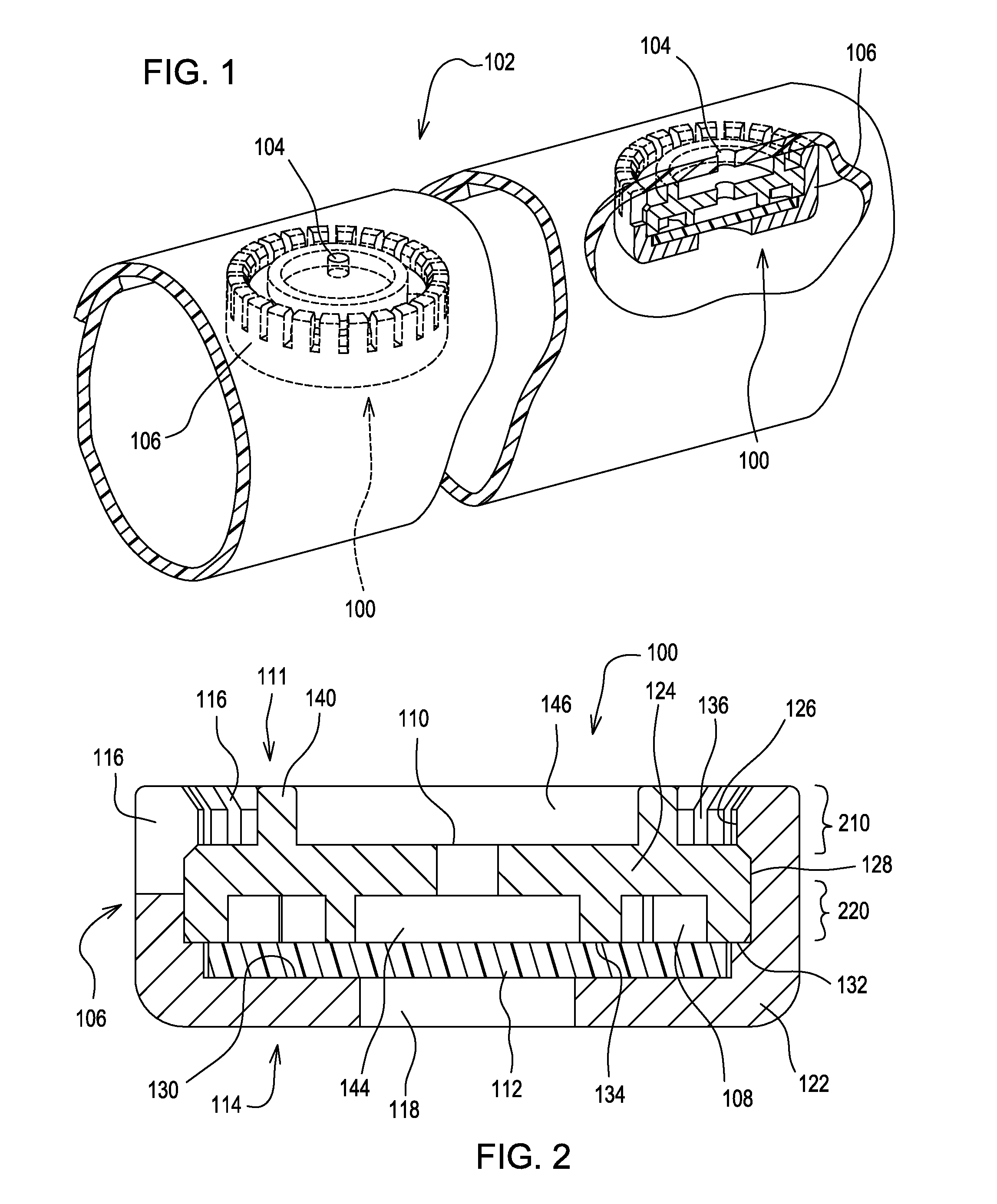
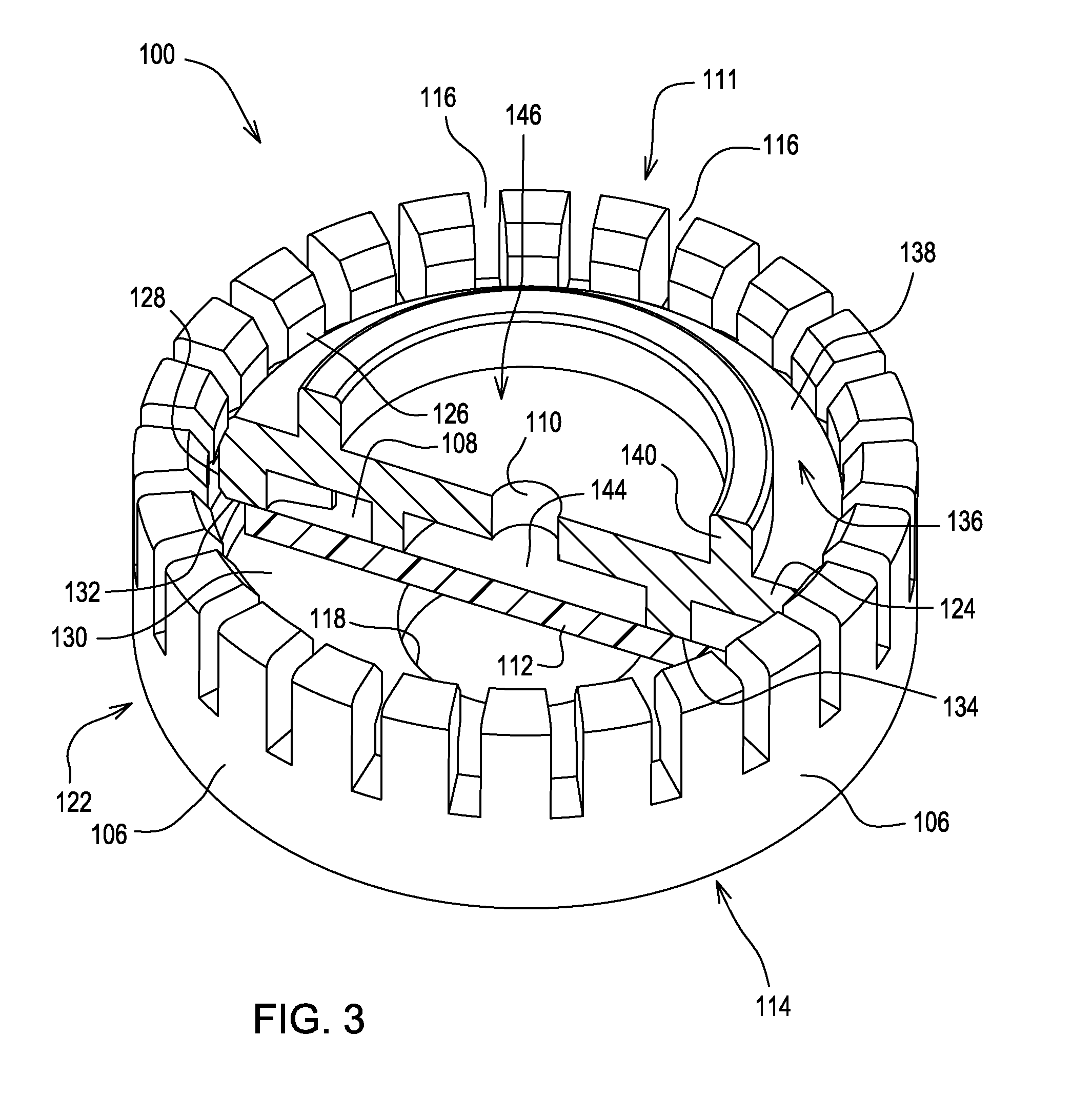
[0016]As shown in FIGS. 1-5, drip irrigation emitter 100 is a pressure regulated drip emitter of small size, preferably having a diameter of less than about 10 mm, and a thickness of less than about 5 mm, and most preferably less than about 3.5 mm. The emitter may be a molded plastic body that may be inserted into thin walled drip tape 102, or any other type of water conduit such as an extruded hose, at regularly spaced intervals during or immediately following extrusion of the drip tape. Each drip irrigation emitter may have a single outlet that may be positioned at an opening 104 that is cut or pre-formed in the wall of the drip tape during production. The emitter is sufficiently low in cost so that it is advantageous for single use applications in which the drip tape may be removed from the field for disposal or recycling after each growing season.

[0017]In the embodiment of FIGS. 1-5, water in thin walled drip tape 102 may enter the emitter by passing through a filter at the emit...


PUM


Abstract

A drip irrigation emitter includes a disc shaped body having a pressure reducing labyrinth between a water inlet area and an outlet hole, and a pressure regulating diaphragm changing flow through the outlet hole in response to water pressure fluctuations in the water conduit where the emitter is mounted. The water filtering inlet of the emitter is located entirely at the sides of the disc shaped body.

Description

FIELD OF THE INVENTION[0001]This invention relates to drip irrigation emitters, also referred to as drippers or emitters, and more specifically to integral drip irrigation emitters that are attached the inner wall of a water conduit.BACKGROUND OF THE INVENTION[0002]Drip irrigation emitters are generally known for use in delivering irrigation water to a precise point at a predetermined and relatively low volume flow rate to conserve water. Drip irrigation emitters may be used in water conduits such as drip tape or extruded pipe, to supply water at a slow, controlled rate to the root zone of the plants being irrigated. The emitters may be inserted into and bonded with the water conduit wall at regular intervals. Each emitter may conduct water from the interior to the exterior of the conduit at a reduced pressure and at a lower rate.[0003]As the water travels through the conduit away from the water source, the water pressure decreases. Water pressure at the beginning of the conduit may...

Claims


Application Information

Patent Timeline
Patent Type & Authority Patents(United States)
IPC IPC(8): B05B15/00
CPCA01G25/023Y02A40/22
Inventor EINAV, ZVIKAHART, JONATHAN D.
Owner RIVULIS PLASTRO LTD
Why Eureka
Try Eureka