Method of configuring an led driver, led driver, led assembly and method of controlling an led assembly

a technology of led fixtures and drivers, applied in the direction of electric discharge lamps, electric variable regulation, instruments, etc., can solve the problems of inconvenient installation, increased installation time, and increased cost, and achieves high efficiency, wealth of functionality, and easy adjustment.

Active Publication Date: 2013-11-12
ELDOLAB HLDG
View PDF13 Cites 35 Cited by
  • Summary
  • Abstract
  • Description
  • Claims
  • Application Information

AI Technical Summary

Benefits of technology

[0009]Yet another object of the present invention is to provide an LED driver applicable in an LED assembly which is better adjusted to adapt to varying user requirements or changes to the LED assembly.
[0042]In an embodiment, the algorithm as provided to the control unit by downloading a program enables the control unit to generate a value for the control signal from a value of the input signal based on one or more parameters of the LED assembly or its environment.
[0043]By determining the relationship between the control signal and the input signal based on an algorithm, the algorithm e.g. applying one or more parameters of the LED assembly or the environment, the behaviour of an LED assembly controlled by a control unit according to the invention can be adjusted easily to varying user requirements or changes to the LED assembly. By downloading the program / algorithm, the control unit can host a wealth of functionality despite limited resources. Limited resources enable miniaturization and or high efficiency. Therefore downloading can be used to further miniaturize or increase efficiency while still having the same degree of applicability of the control unit and thus LED driver over all possible applications.
[0045]A further advantage provided by the control unit according to the invention is that it facilitates the conversion of a comparatively simple input signal (e.g. a single channel input signal) to a more complex output signal and thus a more complex behaviour of the LED assembly. As an example, a single channel input signal (e.g. a DMX signal ranging from 0-255) can result in a multichannel control signal controlling both an intensity and colour of the LED assembly. As an example, the algorithm can convert the input signal to a plurality of control signals for controlling an intensity of a plurality of LEDs having a different colour thereby resulting in the light output of the LED assembly to follow a particular trajectory in the Cx,y space of the chromaticity diagram when the input signal varies from a first value (e.g. zero) to a second value (e.g. a maximum value). The application of an algorithm for determining the relationship between an input signal and a control signal and which can be provided to the control unit by downloading a program thus significantly increases the functionality of the control unit. In an embodiment, the algorithm as applied to establish a control signal for the LED assembly can apply, apart from parameters of e.g. the LED assembly or the environment, one or more feedback signals of the LED assembly to establish the control signal. Such feedback signals can e.g. be obtained from sensors applied in the LED assemble (e.g. temperature or brightness sensors) or can comprise feedback obtained from the LED assembly circuitry, e.g. providing feedback on the voltage over an LED or LED fixture, a current provided by the power converter, etc. In an embodiment, any parameter of the LED assembly or environment as applied in the algorithm can be provided to the control unit by downloading the parameters together with the program providing the algorithm to the control unit. By doing so, the control unit applying the algorithm can easily be adapted to changes made to the LED assembly. Such changes can e.g. include changes to an LED, or LEDs or LED fixture of the LED assembly, or changes to a power converter of the LED assembly or other. As an example, a change in a thermal resistance of the LED assembly to the environment can affect the operation of the LED assembly and can be adjusted by downloading the modified parameter to the control unit. When the control unit is provided with an algorithm using this parameter, the operation of the LED assembly can automatically adjust to the modified parameter.
[0066]In an embodiment of the method of controlling an LED assembly, the LED driver of the LED assembly is configured according to the configuration method according to the invention. In such an embodiment, both the configuration data for configuring the LED driver as the way this data is used in an algorithm for converting an input signal to a control signal can be provided in a flexible manner allowing a user or person installing the LED assembly to easily adjust the behaviour of the LED assembly.

Problems solved by technology

Given the different types of LED assemblies and the different types of LED power supplies (or power converters), installation appears to be prone to errors, which may result in incorrect light output or even damaging of the LED fixture and / or the LED driver, due to exceeding a maximum current, maximum duty cycle, maximum power dissipation etc. of the LED fixture and / or the LED driver.
Whether due to a defective or invalid installation causing a light output which differs from a user's expectations, an incorrect configuration of the LED driver may result in additional cost, additional installation time, waste of valuable resources by damaging power supplies and / or LED assemblies, etc.
Such a predetermined behaviour of the control unit may however render the control unit unsuitable to adjust to changes implemented in e.g. the LED fixture, the power converter or the input signal or when a different response is required / desired by a user.
In addition, such a predetermined behaviour may limit the application of the control unit in a dynamic environment e.g. to control an LED assembly having a modular product concept.

Method used


Image

  • Method of configuring an led driver, led driver, led assembly and method of controlling an led assembly
  • Method of configuring an led driver, led driver, led assembly and method of controlling an led assembly
  • Method of configuring an led driver, led driver, led assembly and method of controlling an led assembly

Examples


Embodiment Construction

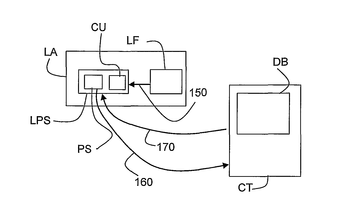
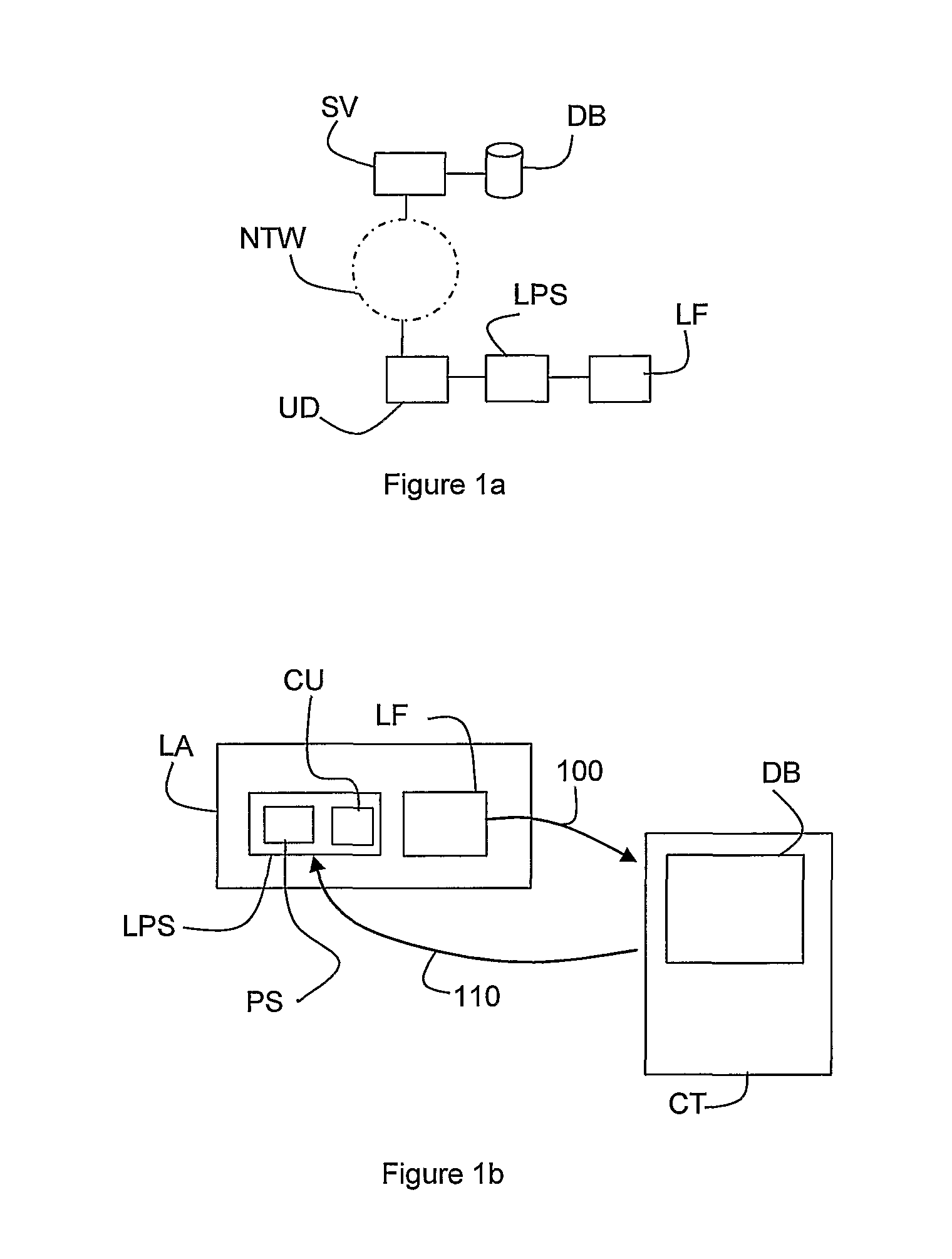
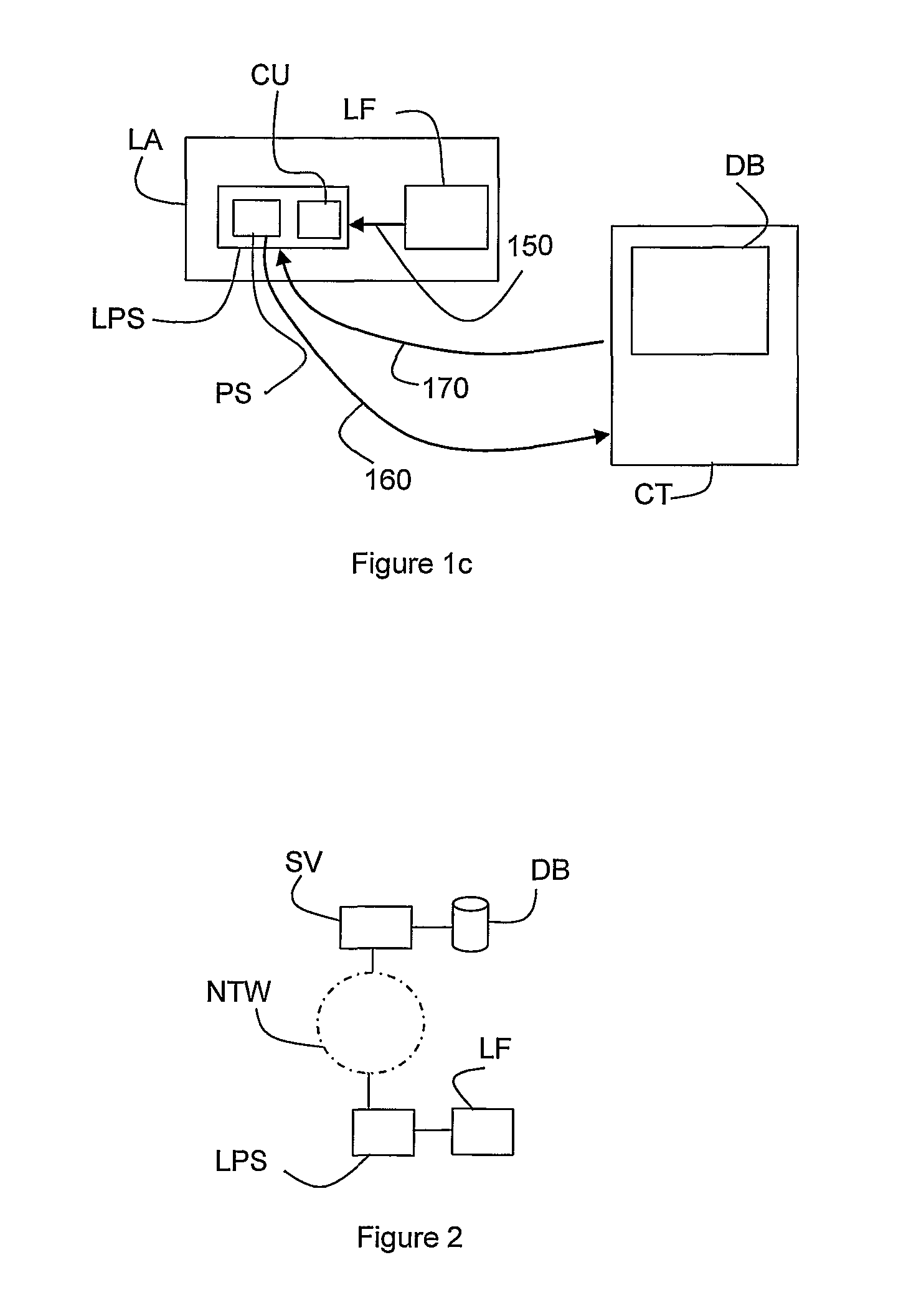
[0073]FIG. 1a depicts a database DB comprising configuration data. The data base is via a server SV (such as a web server or other network server) connected to a communication network NTW, such as the internet, a telecommunication network, a DMX communication bus, etc. The network is connected to a user communication device UD, such as a personal computer, notebook, (e.g. internet enabled) mobile telephone, etc to which an LED driver LPS may be connected. The LED driver is connected to an LED fixture LF to drive it. It is noted that the driving of the LED fixture may comprise providing electrical power to it and / or driving different groups of the LEDs of the LED fixture (e.g. different colors) according to e.g. a users needs. In order to configure the LED driver, the LED driver and / or the LED fixture are to be identified. This may take place in a variety of ways. An identification may for example be sent by the LED driver to the user device UD (either autonomously by the LED driver ...


PUM


Abstract

A method of configuring an LED driver is disclosed. The LED driver being arranged to provide a supply current to an LED fixture comprising a plurality of LEDs. The method comprises: identifying the LED fixture (LF)1 sending via a communication network (NTW) a configuration request to a configuration database (DB), receiving configuration data from the configuration database; and configuring the LED driver (LPS) according to the configuration data.

Description

CROSS-REFERENCE TO RELATED APPLICATIONS[0001]This application is the National Stage of International Application No. PCT / NL2009 / 000219, filed Nov. 17, 2009, which claims the benefit of U.S. Provisional Application Nos. 61 / 115,528, filed Nov. 17, 2008, and 61 / 221,927, filed Jun. 30, 2009, the contents of which are incorporated by reference herein.FIELD OF THE INVENTION[0002]The invention relates to a method of configuring an LED driver, an LED driver, an LED assembly and a method of controlling an LED assembly.BACKGROUND OF THE INVENTION[0003]In the field of LED illumination technology, a variety of products are on the market today. In order to provide an illumination solution for a given application, an installer selects one or more LED assemblies (each comprising a plurality of light emitting diodes (LEDs)) as well as one or more LED drivers in order to drive the LEDs under appropriate electrical conditions. An LED assembly can also be referred to as an LED engine. In order to have...

Claims


Application Information

Patent Timeline
Patent Type & Authority Patents(United States)
IPC IPC(8): H05B37/00H05B44/00
CPCH05B33/083H05B33/0842H05B37/0245H05B37/0272H05B45/48H05B47/175H05B47/19H05B45/3725
Inventor WELTEN, PETRUS JOHANNES MARIASAES, MARC
Owner ELDOLAB HLDG
Why Eureka
Try Eureka