Laser oscillator controller

a laser oscillator and controller technology, applied in lasers, laser beam welding apparatus, manufacturing tools, etc., can solve the problems of poor control resolution of output, unstable laser processing operation, and difficult control of laser oscillators within the range of less than 10% of their maximum rated outpu

Active Publication Date: 2013-12-03
MURATA MASCH LTD
View PDF3 Cites 5 Cited by
  • Summary
  • Abstract
  • Description
  • Claims
  • Application Information

AI Technical Summary

Benefits of technology

[0007]An object of the present invention is to provide a controller for controlling a laser oscillator, which allows for fine adjustment of the output of the laser oscillator as a whole, without modifying the oscillator modules at all.
[0009]Determining the number of modules to be driven allows for reducing the number of oscillator modules to be driven when a low output power is desired. In other words, not all of the oscillator modules have to be driven, and driven modules will be appropriately controlled. In this way, fine control of the output power of a laser oscillator as a whole can be carried out. As a simple example, it is assumed that a laser oscillator includes two oscillator modules and that the output power of each oscillator module can be controllably adjusted by increments or decrements of 10%. Here, when the two oscillator modules operate at the same output powers, the output power of the laser oscillator as a whole can only be adjusted by increments or decrements of 10%. In contrast, when only one of the two oscillator modules is driven and the output power of that particular oscillator module is controllably adjusted by increments or decrements of 10%, then the output power of the laser oscillator as a whole can be adjusted by increments or decrements of 5%. Accordingly, fine adjustment of the output power of a laser oscillator as a whole can be carried out without requiring the use of an oscillator module with a finely controllable output power. Also, the output of an oscillator module normally stabilizes better when it operates at a higher output power, than when it operates at a lower output power. Therefore, driving a smaller number of oscillator modules and designating higher output powers for their operation not only allow for fine adjustment of the output power of the laser oscillator as a whole but also lead to stabilization of the laser output power, which in turn results in a stable laser processing operation. Furthermore, in the case of a laser oscillator whose oscillator modules do not have respective power adjustment capabilities, determining the number of modules to be driven of the plurality of modules enables adjustment of the output power of such a laser oscillator as a whole.
[0011]This allows for choosing the number of the modules to be driven that is appropriate for a required output power of the laser processing machine to perform a given laser processing operation. Thus, a user himself or herself does not have to take current conditions into account and switch the number of driven modules accordingly. Furthermore, by selecting the criteria appropriately, the oscillator modules may be driven in an advantageous number that achieves more effective control of the output power of the laser oscillator.
[0013]Depending on the required output power of the laser oscillator, reducing the number of the modules to be driven may not lead to a meaningful increase in control resolution of an output power of the laser oscillator. In such a case, reducing the number of the modules to be driven only leads to a biased use among the oscillator modules, and this may result in reduced durability of the laser oscillator. On the other hand, by reducing the number of the modules to be driven only when the resolution increases by no less than a predetermined proportion, such reduction of durability due to a biased use among the oscillator modules can be prevented.

Problems solved by technology

When the output power of a laser oscillator is set low relative to its maximum rated output, a laser processing operation becomes unstable.
Normally this is due to poor control resolution of the output of a laser oscillator; for example, control of a laser oscillator within the range of less than 10% of its maximum rated output is very difficult.
This, in turn, makes it difficult to perform fine adjustment of its output in response to changes in the designated value for the output power that occur during a laser processing operation.
In this way, considerable output fluctuations may occur during the processing operation.
As such, fine adjustment is difficult and stable processing quality cannot be achieved.
When moving a laser beam at a lower speed, it may be necessary to reduce the laser output power because otherwise the heat input from the laser beam into a material undesirably increases.
However, the aforementioned limit on the fine adjustment capability does not allow for regulation of the laser output power to a proper level.
The resulting overheating or inadequate heat input jeopardizes a stable processing operation.

Method used


Image

  • Laser oscillator controller
  • Laser oscillator controller
  • Laser oscillator controller

Examples


Embodiment Construction

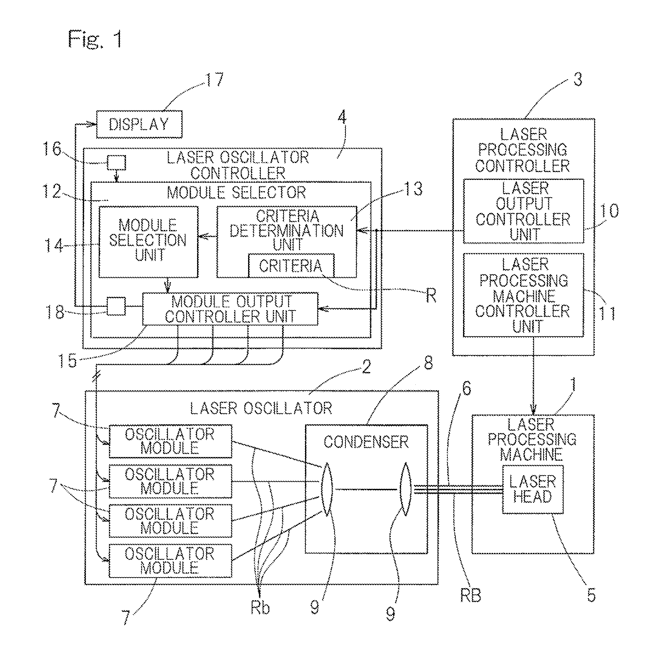
[0026]An embodiment of the present invention will be described in connection with FIGS. 1 to 3. FIG. 1 shows a block diagram of a schematic configuration of a laser processing system in its entirety. The laser processing system may include a laser processing machine 1, a laser oscillator 2, a laser processing controller 3 that controls the laser processing machine 1, and a laser oscillator controller 4 that controls the laser oscillator 2. The laser processing machine 1 may include, for example, a laser cutting machine for cutting sheet materials, a laser engraving machine for engraving patterns or markings, a laser drilling machine for drilling holes in a substrate, a laser ablation machine for ablating off the outer surface of a solid object, a laser welding machine for performing a laser welding operation, etc. The laser processing machine 1 may include a laser head 5 that directs a laser beam to a workpiece (not shown). If the laser processing machine 1 includes a laser cutting ...


PUM

PropertyMeasurementUnit
output powersaaaaaaaaaa
poweraaaaaaaaaa
poweraaaaaaaaaa

Abstract

Provided is a method for controlling a laser oscillator. Such a laser oscillator is applicable to a laser processing machine and includes a plurality of oscillator modules each adapted to be driven to oscillate a laser beam. Also, such a laser oscillator is configured to collect laser beams oscillated by driven modules for output. The method includes determining the number of modules to be driven, of the plurality of oscillator modules.

Description

CROSS REFERENCE TO THE RELATED APPLICATION[0001]This application is based on and claims priority to Japanese patent application No. 2011-093684, filed on Apr. 20, 2011, the entire disclosure of which is herein incorporated by reference as a part of this application.FIELD OF THE INVENTION[0002]The present invention relates to a controller for controlling a laser oscillator that is applicable to a laser processing machine that processes, for to example, sheet metals.BACKGROUND OF THE INVENTION[0003]A laser oscillator for laser processing application may include a couple of oscillator modules each operable to oscillate a laser beam, so that the laser beams oscillated by these oscillator modules can be collected for output. Each of such oscillator modules by itself can adequately provide for a laser oscillator, as well. Such oscillator modules are often combined to provide for a laser oscillator of a significant output that cannot be achieved with a single oscillator module, and a numbe...

Claims


Application Information

Patent Timeline
Patent Type & Authority Patents(United States)
IPC IPC(8): H01S3/00H01S3/13H01S3/23
CPCB23K26/0613H01S3/2383H01S3/10069
Inventor SENDA, TAKASHI
Owner MURATA MASCH LTD
Why Eureka
Try Eureka