Bladed fishing lure assembly

a technology of rods and components, applied in the direction of fishing, lines, animal husbandry, etc., can solve the problem of relative ineffective frequency determination

Inactive Publication Date: 2015-03-10
THORNE DAVID L
View PDF32 Cites 8 Cited by
  • Summary
  • Abstract
  • Description
  • Claims
  • Application Information

AI Technical Summary

Benefits of technology

[0031]In one of these embodiments, the weight is not directly affixed to the blade. In such cases, a less robust and more easily breakable blade may be used without stresses of the weight bearing directly on the blade.
[0041]The frame part comprises a vertical mast which is medially disposed on distal side of the blade when assembled in combination with the blade to provide support and maintain vertical disposition of the flexible blade against rigors of fishing as the blade is displaced through water. In addition, the frame part comprises an angulated structure inferior to the mast which is bent to provide an arduous pathway over which the blade is threaded for secure engagement upon the frame, once so disposed. Once mounted on the frame, angulation of the frame and relaxation of the blade to its substantially original form keeps the blade securely affixed thereto. The blade only requires two holes through which the frame and associated mast is inserted for connection and is sufficiently flexible to permit such attachment of blade to frame. Generally, in this manner, a flexible blade may be made from a clear pliable plastic, such as mylar or polyester. Also, blade oscillation is unencumbered by a weight which may be affixed to the frame for fishing level and luer stability control.

Problems solved by technology

So disposed, the weight determines orientation of the assembly in water and effectively acts as a stabilizing fulcrum as the assembly is retrieved through the water while being relatively ineffective in determining frequency of oscillation of the blade, yaw divergence of the blade and each associated trailing portion.

Method used


Image

  • Bladed fishing lure assembly
  • Bladed fishing lure assembly
  • Bladed fishing lure assembly

Examples


first embodiment

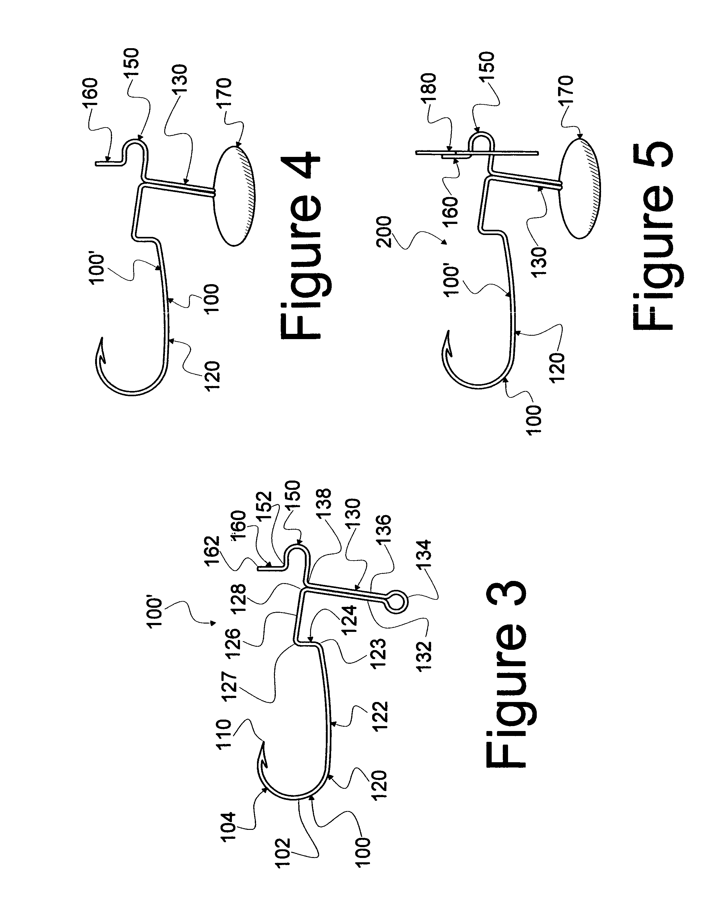
[0078]Reference is now made to FIGS. 3-9 wherein the instant invention disclosed herein is seen in various aspects. In FIG. 3, a fishhook 100, which is one continuous, sturdy wireform frame 100′, is seen. At a distal end 102, frame 100′ comprises a curved section 104 which rises dorsally to a point 110. Proximally contiguous with section 104, frame 100′ comprises a bent shaft 120 (although shaft 120 may be formed in many ways consistent with the instant invention.) Shaft 120 therefore comprises a distal elongated, substantially horizontal section 122 contiguously affixed to an upwardly distending section 124 at a bend 123. Section 124 is further contiguously affixed to another proximally distending section or segment 126 at a bend 127. Section 126 (and shaft 120) is abruptly terminated proximally at a bend 128.

[0079]Contiguous at bend 128 another section of frame 100′ is inferiorly disposed to provide a tethering segment 130. Segment 130 comprises an inferiorly distending segment 13...

third embodiment

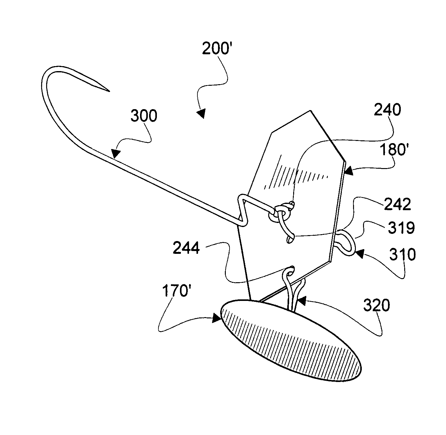
[0090]Reference is now made to FIGS. 13-17 wherein parts and combinations of parts of a third embodiment, assembly 200″, of the instant invention are seen. A two hole blade 180″ is seen in FIG. 13. Blade 180″ is similar in all respects to blade 180′ except that blade 180″ does not comprise a hole 242. As seen in FIG. 14, a weight 170′ is affixed to blade 180″ via a strap 320 disposed through hole 244, as is the case for connecting weight 170′ to blade 180′, as previously disclosed.

[0091]A connecting elongated shaft 350 is disposed to communicate through hole 240. Generally, though not universally, a connecting ring 352 is affixed to a distal end 354 of shaft 350 (which may be best seen in FIG. 16). Similarly, another connecting ring 356 may be connected at the proximal end 358 of shaft 350. At least one hollow, elongated spacer 360 is disposed along shaft 350 proximal to blade 180″. Another hollow elongated spacer 360 and an associated bead (not seen in the figures, but well known i...


PUM


Abstract

A fishing lure assembly is disclosed which comprises a blade free to oscillate, yaw and produce a trailing wake as the fishing lure assembly is displaced through water. A weight is affixed to the fishing lure assembly, but inferiorly disposed such that the blade is free to oscillate and have a yaw divergence which is substantially unaffected by inertia of the weight. The fishing lure may be variably constructed to include one or more hooks and soft bait and hard bait bodies which are disposed to follow behind in the trailing wake. In one embodiment, a float is added to the lure assembly. In another embodiment, a combination of a frame and blade is disclosed, the blade being flexible and resilient and affixed to the frame such that the blade is securably affixed but replaceable in a fishing environment.

Description

CONTINUITY[0001]This application is a Continuation-in-Part of U.S. patent application Ser. No. 11 / 656,099, titled FISHING LURE ASSEMBLY and filed Jan. 22, 2007 by David L. Thorne. Currently, election of U.S. patent application Ser. No. 11 / 656,099 relies specifically upon the species seen in FIGS. 10-12 of this application.FIELD OF INVENTION[0002]This invention relates to weighted assemblies from which fishing lures or other fishing gear may be assembled, and particularly assemblies which comprise an oscillating blade affixed to a trailing portion of a lure which is actuated by movement of the blade through water.BACKGROUND AND RELATED ART[0003]Fishing lures for jigging are well known in fishing art. Such lures are generally made by casting or otherwise enveloping a shank of a hook with a weighted (usually metal) body. Examples of such lures are disclosed in U.S. Pat. No. 4,453,333 issued Jun. 12, 1984, to Robert W. Olson (Olson). Olson also discloses a generally convex blade to whic...

Claims


Application Information

Patent Timeline
Patent Type & Authority Patents(United States)
IPC IPC(8): A01K85/00A01K85/01A01K85/14A01K85/16A01K85/18
CPCA01K85/00A01K85/14A01K85/16A01K85/18A01K85/01
Inventor THORNE, DAVID L.
Owner THORNE DAVID L
Why Eureka
Try Eureka