Training cartridge

a technology of training cartridges and cartridge parts, which is applied in the direction of blasting cartridges, cartridge ammunition, weapons components, etc., can solve the problem of limiting the choice of materials from which any thin section part of the cartridge assembly can be manufactured, and achieve the effect of facilitating efficient live round ejection

Active Publication Date: 2013-02-05
UTM IP
View PDF22 Cites 12 Cited by
  • Summary
  • Abstract
  • Description
  • Claims
  • Application Information

AI Technical Summary

Benefits of technology

[0012]The posterior portion is desirably comprised from a brass or steel providing a centre of gr

Problems solved by technology

This limits the choice of materials from which any thin section part of the cartridge assembly ca

Method used


Image

  • Training cartridge
  • Training cartridge

Examples


Embodiment Construction

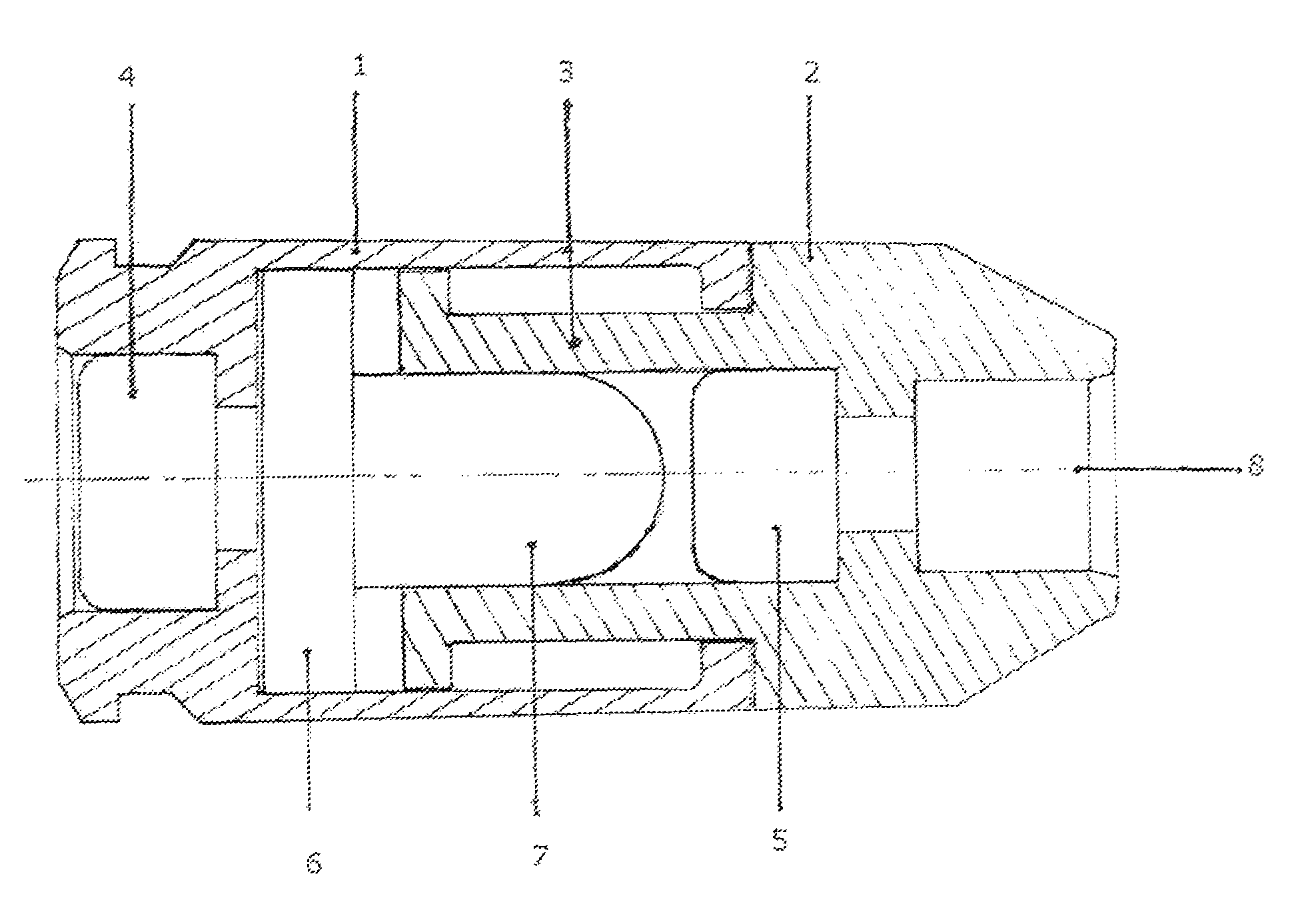
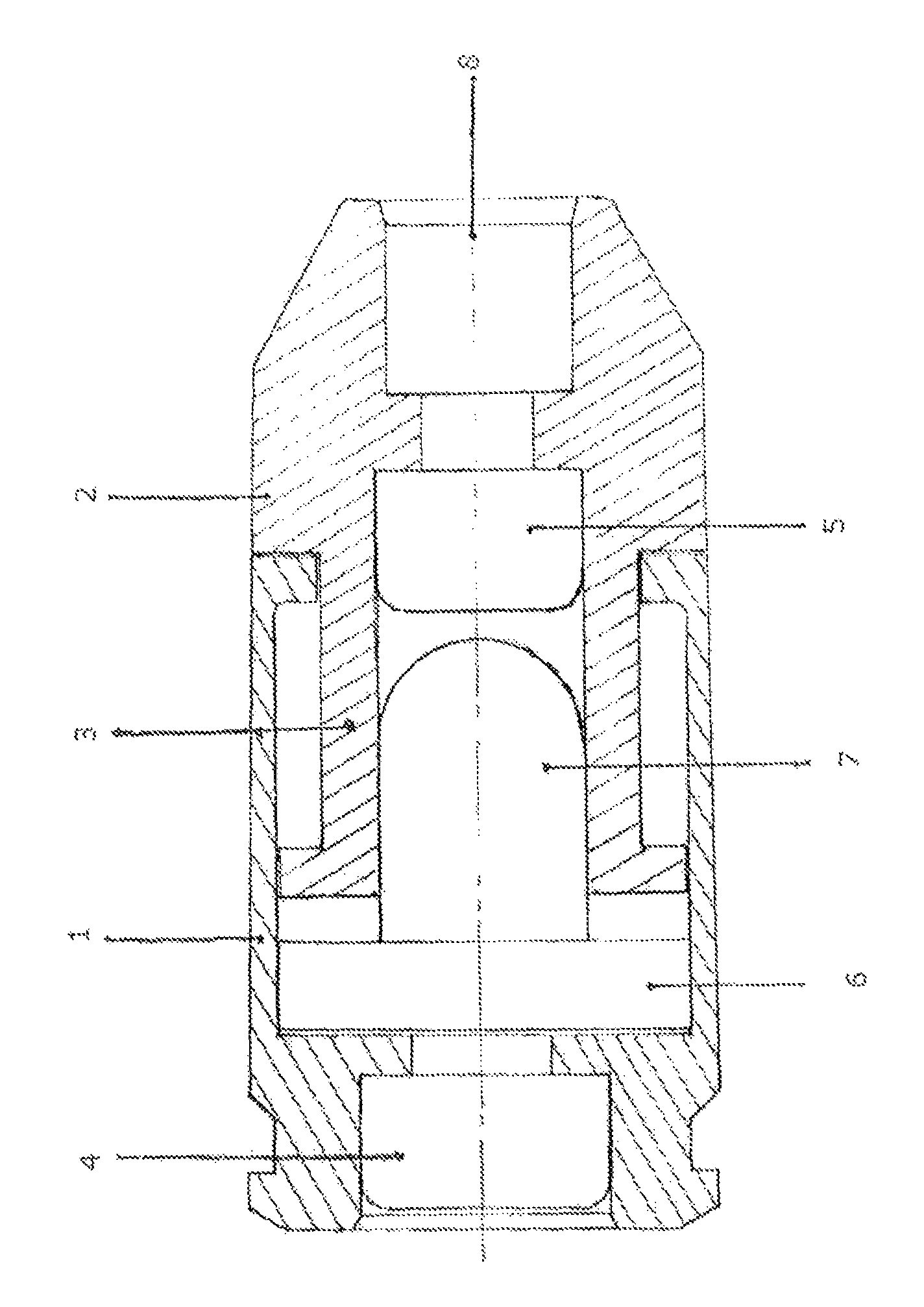
[0015]As can be seen from FIG. 1, a cartridge comprises a posterior portion 1 which extends axially to provide a cylindrical casing. An anterior portion comprises of a nose portion 2 with a centrally located recess 8 for receiving a projectile, and an axially extending piston 3 which is slidably engaged in the chamber defined by the cylindrical casing 1. A posterior primer 4 is located to the end of the posterior portion which is most distal to the nose portion 2. An anterior primer 5 sits just behind the recess 8 of the nose portion 2. A plastic striker is located in the chamber defined by the cylindrical casing 1 and comprises of a sealing flange portion 6 and striking nose portion 7. The striking nose portion 7 locates snugly but slidably in a second chamber provided axially within the piston 3.

[0016]In use, posterior primer 4 is initiated on firing of a host firearm. Gas product from the posterior primer 4 expands driving the cylindrical casing in a first axial direction and the...


PUM


Abstract

A cartridge for non-lethal applications comprises a posterior portion 1 which extends axially to provide a cylindrical casing. An anterior portion comprises of a nose portion 2 with a centrally located recess 8 for receiving a projectile, and an axially extending piston 3 which is slidably engaged in the chamber defined by the cylindrical casing 1. A posterior primer 4 is located to the end of the posterior portion which is most distal to the nose portion 2. An anterior primer 5 sits just behind the recess 8 of the nose portion 2. A plastic striker is located in the chamber defined by the cylindrical casing 1 and comprises of a sealing flange portion 6 and striking nose portion 7. The striking nose portion 7 locates snugly but slidably in a second chamber provided axially within the piston 3. In use, the posterior primer 4 releases gaseous product which drives the striker 7 against the anterior primer 5 while simultaneously causing telescopic extension of the cartridge which in turn results in recycling of a host firearm.

Description

BACKGROUND OF THE INVENTION[0001]This invention relates to training cartridges, most particularly to training cartridges which recycle the host firearm by telescopic expansion of the cartridge.[0002]Telescopically expanding training cartridges are known, one example is described in the applicant's own U.S. Pat. No. 6,564,719 B2. A typical cartridge of the type described in that patent comprises a posterior portion which has a moveable member which is slidable rearwardly towards a breech block of a host firearm. The anterior portion has a gas passage there through and an expansion chamber is provided between the moveable member and the anterior portion. Gas generating means for providing gas within the cartridge are initiatable on firing of the firearm to propel the moveable member in a rearward direction so as to recycle the firearm. A second gas generating means is positioned forward of the gas passage and may be initiated by any suitable reaction caused on initiation of the poster...

Claims


Application Information

Patent Timeline
IPC IPC(8): F42B5/045
CPCF42B5/045F42B8/02
Inventor SAXBY, MICHAEL ERNEST
Owner UTM IP
Why Eureka
Try Eureka