
Apparatus for Supporting a Parachute Flight Controller and Flight Controller for a Parachute

a flight controller and parachute technology, applied in the field of flight or guidance controllers, can solve problems such as inability or convenience, and achieve the effects of reducing the number of components required, compactness, and reducing the number of components

Active Publication Date: 2012-06-14
MIST MOBILITY INTEGRATED SYST TECH MMIST
View PDF5 Cites 11 Cited by
  • Summary
  • Abstract
  • Description
  • Claims
  • Application Information

AI Technical Summary

Benefits of technology

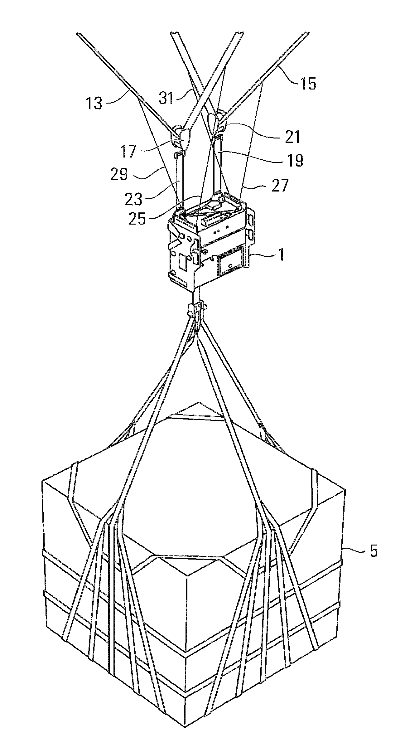
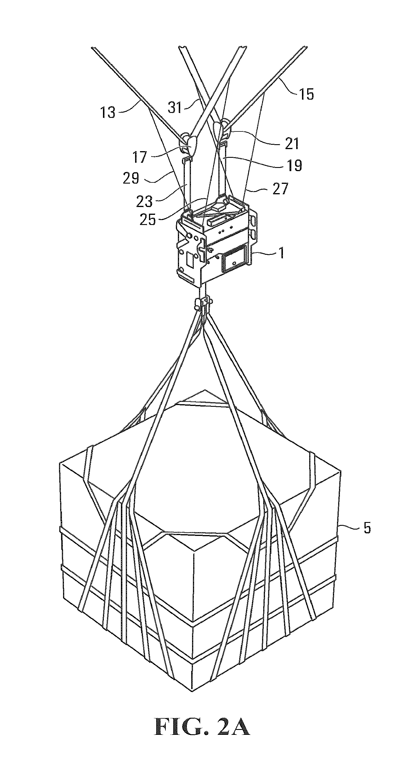
[0005]This arrangement enables the mechanism of a flight controller that controls the direction of a parachute to be removed from the load path between the parachute and its payload. Thus, rather than the payload being connected to the parachute through control lines of a flight controller, the payload can be independently connected to the parachute and supported thereby through the bearing member and the support member. The arrangement allows the control lines or another mechanism of the flight controller to control relative movement between the bearing member and the support member so that the length of the support member on either side of the bearing member can be varied, which in turn results in relative vertical displacement between the first and second suspension lines and corresponding vertical displacement of the portion of the parachute canopy to which they are attached. Advantageously, by removing the control mechanism of the flight controller from the load path, the mechanism can be less robust and made from smaller and light components thereby enabling the flight controller to be lighter and more compact. In turn, this enables a larger payload to be accommodated within a given volume allocated to a payload package including the parachute, flight controller and payload. This arrangement also potentially allows heavier payloads to be carried by the parachute.
[0052]Similarly, although the second and fourth pulleys may be driven by separate drive means, e.g. separate electric motors, in other embodiments, the second and fourth pulleys may both be driven by the same drive means, e.g. the same electric motor. Again, this reduces the component count with attendant benefits.

Problems solved by technology

This method of deployment removes the need for the aircraft to land, which might not be possible or convenient, depending on the terrain and availability of a suitable runway and ground support.

Method used


Image

  • Apparatus for Supporting a Parachute Flight Controller and Flight Controller for a Parachute
  • Apparatus for Supporting a Parachute Flight Controller and Flight Controller for a Parachute
  • Apparatus for Supporting a Parachute Flight Controller and Flight Controller for a Parachute

Examples


Embodiment Construction

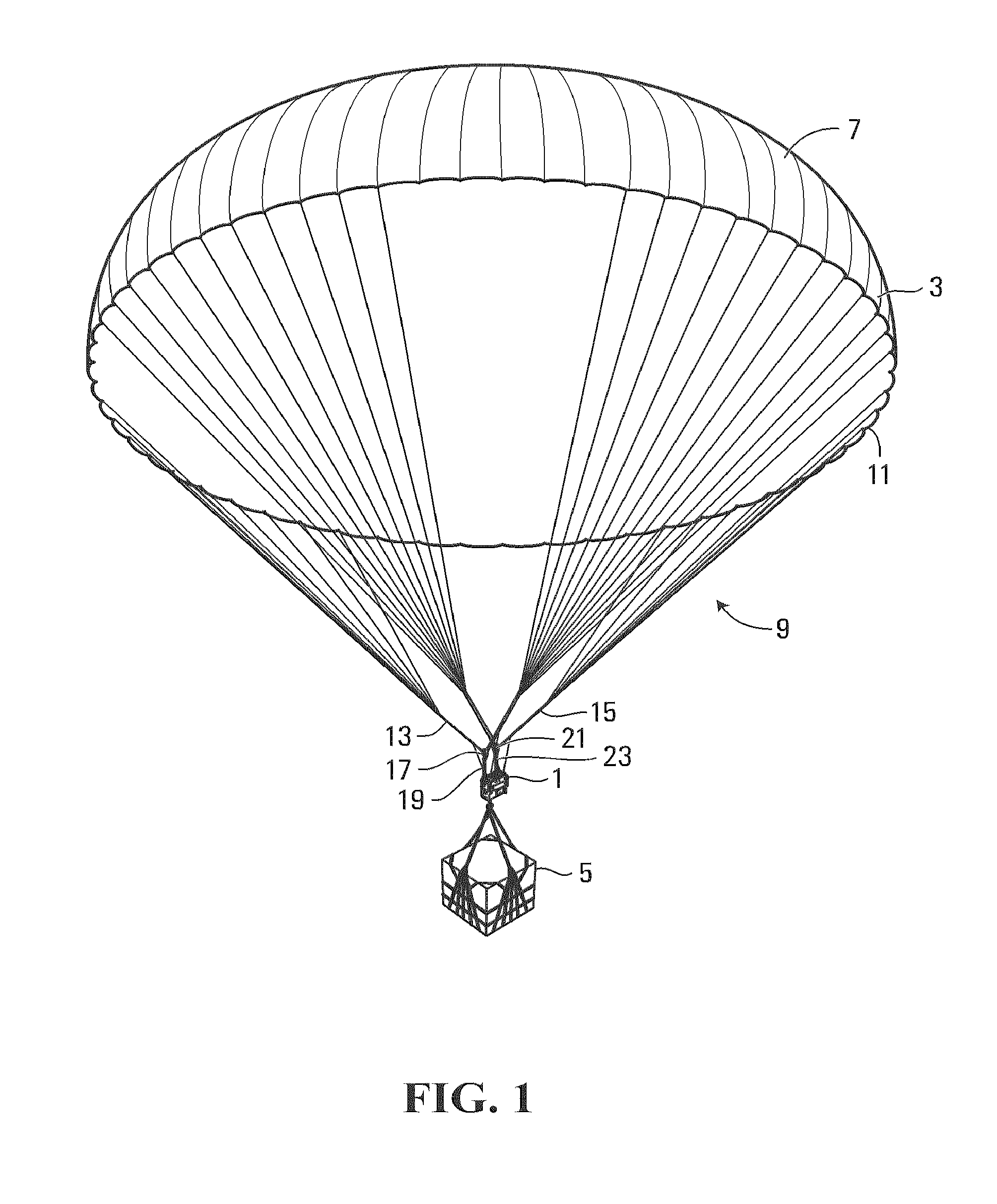
[0142]FIG. 1 shows a flight control unit 1 according to an embodiment of the present invention suspended beneath a round parachute 3 carrying a payload 5. The parachute 3 has a canopy 7 and suspension lines 9 extending downwardly from the peripheral edge 11 of the canopy. The suspension lines are divided into four groups, with the suspension lines of each group being associated with a particular quadrant of the canopy 7. A first support member, for example, a first coupling line or sling 13 is connected between the suspension lines of a first quadrant and the suspension lines of a third, opposite quadrant. A second support member, for example, a second coupling line or sling 15 is connected between the suspension lines of a second quadrant and the suspension lines of an opposite, fourth quadrant. A first bearing member, for example a first pulley 17 which is connected to a first riser 19 is positioned on the first coupling line or sling 13, and a second bearing member, for example, ...


PUM


Abstract

An apparatus for supporting a parachute flight controller from a parachute comprises a bearing member, for example a pulley, a load-bearing coupling, for example a harness, connected to the bearing member and including a connector for connecting the coupling to a parachute flight controller. The coupling includes a load-bearing connector for connecting a payload thereto, and the bearing member is adapted to enable relative movement, controlled by the flight controller, between the bearing member and a support member, for example a flexible coupling line or web for supporting the bearing member connected between first and second suspension lines of a parachute. The flight controller may include one or more control lines connected to the support member or suspension lines which can be wound in or out of the flight controller to effect relative movement between the bearing member and the support member and thereby control the direction of the parachute.

Description

FIELD OF THE INVENTION[0001]The present invention relates to flight or guidance controllers for parachutes and other drag devices, and in particular, but not limited to flight controllers that enable parachutes with payloads to be steered according to a desired flight path towards a desired target location.BACKGROUND OF THE INVENTION[0002]Equipment, supplies and other items may be efficiently delivered to a desired location by dropping them from aircraft and using parachutes to slow their descent to bring them safely to ground. This method of deployment removes the need for the aircraft to land, which might not be possible or convenient, depending on the terrain and availability of a suitable runway and ground support. The parachute guidance system may be used to steer the parachute and its cargo towards a desired location during its flight. An example of an aerial delivery device having a parachute guidance system is described in U.S. Pat. No. 7,059,570 to Strong. The delivery devi...

Claims


Application Information

Patent Timeline
Patent Type & Authority Applications(United States)
IPC IPC(8): B64D17/22B64D17/00
CPCB64D17/343B64D17/025B64D1/08
Inventor MCCANN, SEANBAUMEISTER, PETER
Owner MIST MOBILITY INTEGRATED SYST TECH MMIST
Learn More