Imaging and display system for vehicle

a technology for displaying systems and vehicles, applied in television systems, instruments, transportation and packaging, etc., can solve the problems of requiring complexity and cost, affecting the situation of drivers, and the inability of drivers to view overtaking vehicles, etc., and achieve the effect of improving driver's situational awareness

Active Publication Date: 2015-05-26
MAGNA ELECTRONICS
View PDF547 Cites 122 Cited by
  • Summary
  • Abstract
  • Description
  • Claims
  • Application Information

AI Technical Summary

Benefits of technology

[0006]For example, the video display screen may be operable or addressable in at least two (and optionally and preferably at least three) addressable or operable or actuatable zones or regions (such as a left region, a center region and a right region) to display respective portions of the rearward images captured by the rear backup camera at the rear of the equipped vehicle. The two or three (or more) zones or regions of the video display screen may have similar or different cross dimensions depending on the particular application and desired display options of the vision and display system. Optionally, the video display screen (either at a zone or region that is currently displaying video images or at one of the zones or regions that is not currently displaying video images) may display an iconistic representation of the equipped vehicle (either as an addition / enhancement to or a replacement for the real time video display of video images captured by the rear camera) and / or an alert or warning indication / signal to further enhance the driver's cognitive recognition and awareness of the displayed scene at the mirror assembly or at another display location in the vehicle.
[0008]Optionally, the video display screen may display video images of the local region or area rearward and sideward of the equipped vehicle at a portion of the video display screen and may display an iconistic display or alert or graphic overlay at that portion of the video display screen and / or at another portion of the same or common video display screen to alert the driver of the equipped vehicle and to enhance the driver's cognitive awareness of the purpose of the video images being displayed by the video display screen and to enhance the driver's situational awareness of vehicles approaching or in a side lane blind spot when the driver is contemplating and / or is executing a lane change maneuver into that adjacent side lane. For example, if the system detects another vehicle at or approaching to the rear and left side of the equipped vehicle (or if the driver actuates a turn signal indicating a lane change into that side lane), the video display screen may display a left side region of the captured rearward image at a left side or portion of the video display screen and may display an iconistic representation of a vehicle to the left and rear of a subject vehicle at the right side of the video display screen, to enhance the driver's cognitive awareness and understanding of the displayed image.
[0009]Optionally, and preferably, the video display screen may be disposed at or in an interior rearview mirror assembly of the vehicle and behind a mirror reflective element. Optionally, the video display screen, when operated to display images or information, may be viewable through a transflective mirror reflector of a reflective element of the mirror assembly. The portion of the video display screen that displays the video images (such as via backlighting of a liquid crystal video display or the like) may be viewable through the transflective mirror reflector while the portion of the video display that does not display video images may be dark (i.e., may be non-emitting) or otherwise non-displaying or not actuated, or may display non-video information, such as an iconistic representation of what may be happening about the vehicle or a graphic overlay or the like. The driver viewing the mirror at the non-video displaying portion of the video display screen views a reflected image as reflected by the transflective mirror reflector of the mirror reflective element other than where non-video information may be being displayed, thus maximizing the rear vision capability of the interior mirror while the driver is driving down the road or highway. In this regard, having a high contrast ratio for the video display device used is beneficial and is preferred. The vision and display system of the present invention thus provides a blind spot side lane display or alert at the interior rearview mirror assembly without substantially interfering with the driver's rearward field of view at the mirror reflective element of the interior rearview mirror assembly.
[0011]Optionally, the video processor of the system may include a decoder that decodes a NTSC signal from the rearward facing camera or image sensor of the vehicle. The decoder may have a microprocessor that is operable to control the video display screen, such that the images are processed and displayed with a common microprocessor, thereby obviating the need for a separate microprocessor for the video display screen. The decoder may be operable to at least provide on screen display capability, provide video decoding, at least partially control dimming of the transflective electrochromic mirror reflective element, and at least partially control the intensity of the video display screen.
[0012]Therefore, the vision system or display system of the present invention provides a combined rear vision system or blind zone display or backup assist system and a side lane blind spot vision system or lane change assist system that utilizes a single or common rearward facing camera at the rear of the vehicle, and preferably provides display at a single or common video display of the vehicle in a manner that is cognitively recognizable, appreciable and usable by the driver of the equipped vehicle. The image data captured by the rearward facing camera may be processed to display rearward images of the scene behind the vehicle when the vehicle is shifted into reverse and during a reversing maneuver, and the video image data captured by the rearward facing camera may be processed and cropped or manipulated to display rearward and sideward video images of the scene rearward and sideward of the equipped vehicle to alert the driver of the presence of another vehicle at or in or approaching the equipped vehicle at that side of the vehicle, such as responsive to the driver of the equipped vehicle actuating a turn signal indicator to change lanes while driving along a road or responsive to detection of another vehicle at the side or rear or at or near or approaching a side blind spot area of the equipped vehicle. Graphics, icons and / or other overlays or computer generated indicia may be generated and co-displayed with the captured video image or portion of the captured video image in a manner that is accretive to and that enhances the driver's situational awareness to the rear and to the side of the equipped vehicle.

Problems solved by technology

Road safety issues associated with side lane blind spots are known.
The driver of the vehicle usually is not able to view the overtaking vehicle in the driver's side view mirror due to the restricted field of view provided by that side view mirror.
Such prior systems involve mirrors and / or multiple cameras and multiple displays, and thus require complexity and cost.

Method used


Image

  • Imaging and display system for vehicle
  • Imaging and display system for vehicle
  • Imaging and display system for vehicle

Examples


Embodiment Construction

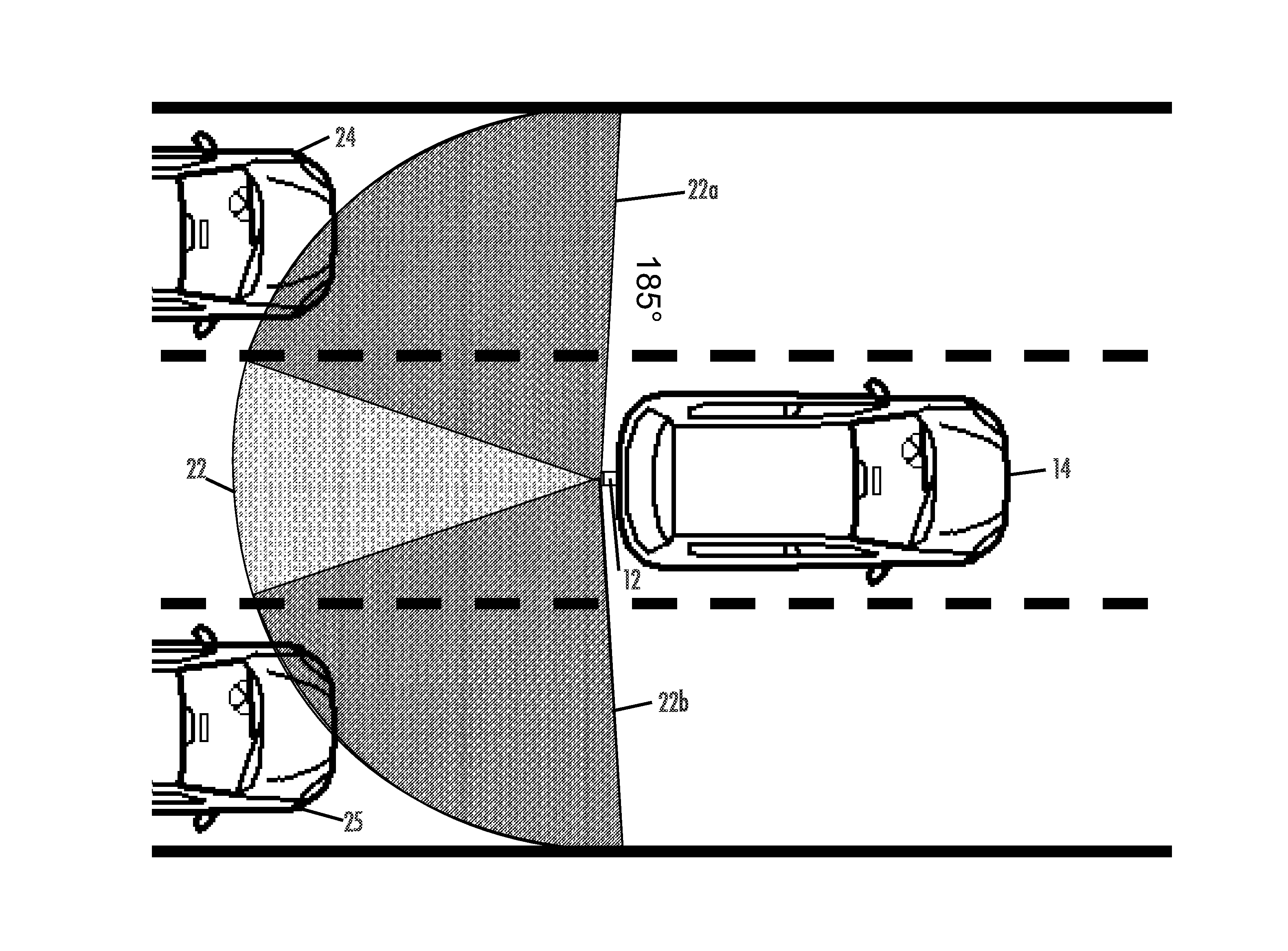
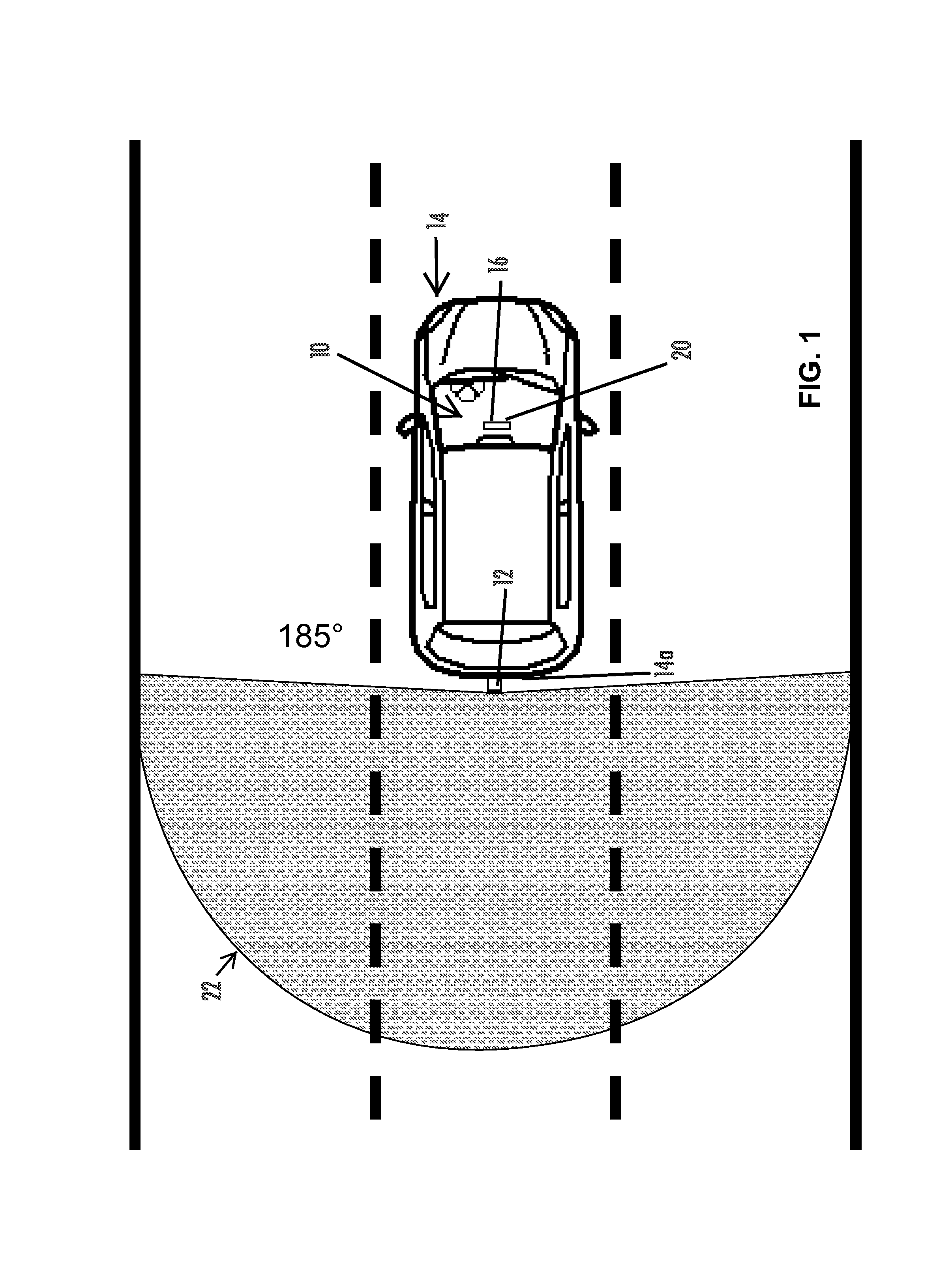
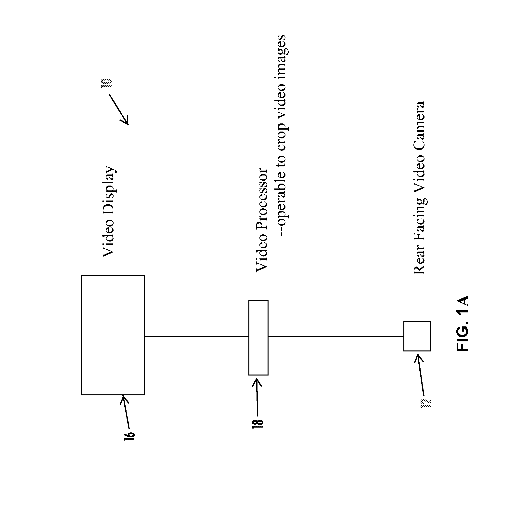
[0041]Referring now to the drawings and the illustrative embodiments depicted therein, a vehicular vision system 10 includes a rearward facing video camera or imaging sensor 12 disposed at a rear portion 14a of a vehicle 14, a video display screen 16 disposed at an interior cabin of the vehicle and at or near the windshield 14b of the vehicle, and a video processor 18 for processing image data captured by the rearward facing camera 12 (FIGS. 1 and 1A). The video display screen 16 is responsive to the video processor 18 (which may be operable to crop the video images, may be operable for machine vision objection detection, may be operable for electronic image distortion reduction and / or may be operable for graphic overlay generation) and is operable to display video images captured by the rearward facing camera 12 for viewing by the driver of the vehicle when the driver is normally operating the vehicle. The video display screen 16 may, responsive to the driver of the vehicle shiftin...


PUM

PropertyMeasurementUnit
rearward field of viewaaaaaaaaaa
wide angleaaaaaaaaaa

Abstract

A vehicular imaging and display system includes a rear backup camera at a rear portion of a vehicle, a video processor for processing image data captured by the rear camera, and a video display screen responsive to the video processor to display video images. During a reversing maneuver of the equipped vehicle, the video display screen displays video images captured by the rear camera. During forward travel of the equipped vehicle, the video display screen is operable to display images representative of a portion of the field of view of the rear camera to display images representative of an area sideward of the equipped vehicle responsive to at least one of (a) actuation of a turn signal indicator of the vehicle, (b) detection of a vehicle in a side lane adjacent to the equipped vehicle and (c) a lane departure warning system of the vehicle.

Description

CROSS REFERENCE TO RELATED APPLICATIONS[0001]The present application is a 371 U.S. national phase filing of PCT Application No. PCT / US10 / 47256, filed Aug. 31, 2010, which claims the benefit of U.S. provisional application Ser. No, 61 / 351,513, filed Jun. 4, 2010, and Ser. No. 61 / 238,862, filed Sep. 1, 2009, which are hereby incorporated herein by reference in their entireties.FIELD OF THE INVENTION[0002]The present invention relates generally to the field of vision systems and display systems for vehicles.BACKGROUND OF THE INVENTION[0003]Road safety issues associated with side lane blind spots are known. Drivers often attempt or execute a side lane change maneuver unaware of the presence of another vehicle overtaking the vehicle in the immediate adjacent side lane. The driver of the vehicle usually is not able to view the overtaking vehicle in the driver's side view mirror due to the restricted field of view provided by that side view mirror. The overtaking vehicle, not being visible...

Claims


Application Information

Patent Timeline
Patent Type & Authority Patents(United States)
IPC IPC(8): H04N7/18G02F1/1335G08G1/16B60R1/00B60R1/04B60R1/12G08G1/0962
CPCB60R1/00B60R1/04G08G1/09623G08G1/09626G08G1/167H04N7/181B60R2001/1215B60R2300/806B60R2300/8066B60R2001/1253B60R2300/70B60R2300/802H04N7/183B60R1/08
Inventor BAUR, MICHAEL J.BLANK, RODNEY K.LARSON, MARK L.LYNAM, NIALL R.
Owner MAGNA ELECTRONICS
Why Eureka
Try Eureka