Method and apparatus for end node assisted neighbor discovery

a technology of neighbor discovery and end node, applied in the field of communication system, can solve the problems of inefficiency, delay in handoff, packet loss, etc., and achieve the effect of facilitating the phased deployment of access nodes

Active Publication Date: 2015-07-07
QUALCOMM INC
View PDF437 Cites 0 Cited by
  • Summary
  • Abstract
  • Description
  • Claims
  • Application Information

AI Technical Summary

Benefits of technology

[0009]By automating all or a portion of the access node discovery process, the methods and apparatus of the present invention make phased deployment of access nodes easier than in systems where access nodes must be manually programmed and / or supplied with information about their neighbors as part of the process of deploying a new base station. In addition, since the neighbor discovery and updating process occurs with little or no direct administrator involvement, the methods and apparatus of the present invention are particularly well suited for systems where the entire network may not be under control of a single administrator and individuals may freely add access nodes, e.g., base stations, at will, without first notifying other base station administrators of the introduction of a new base station into the system.

Problems solved by technology

This approach results in handoff delays and packet loss when the end node is only able to maintain one single bidirectional communications link at the time.
This approach, in some cases, is inefficient since links, especially when they are wireless links, tend to fluctuate in terms of quality (e.g., delay and loss characteristics).
As a result the link to the target destination access node may not be the best link available to the end node at the time a message to said target destination access node needs to be sent.
This approach of using network layer addresses is also inefficient especially when the messaging has to do with link layer specific functions, since network layer messages tend to be much larger than link layer messages in some systems.
Such inefficient signaling is not well suited for communications over resource restricted air links.
Such configuration is typically labor intensive and error prone not only due to possible human error but also due to the fact that the network layout of a wireless network often changes by network expansion or even due to environmental conditions.

Method used


Image

  • Method and apparatus for end node assisted neighbor discovery
  • Method and apparatus for end node assisted neighbor discovery
  • Method and apparatus for end node assisted neighbor discovery

Examples


Embodiment Construction

[0022]The methods and apparatus of the present invention for routing messages based on physical layer information, e.g., physical layer identifiers, which can be used to support communications sessions with one or more end nodes, e.g., mobile devices. The method and apparatus of the invention can be used with a wide range of communications systems. For example the invention can be used with systems which support mobile communications devices such as notebook computers equipped with modems, PDAs, and a wide variety of other devices which support wireless interfaces in the interests of device mobility.

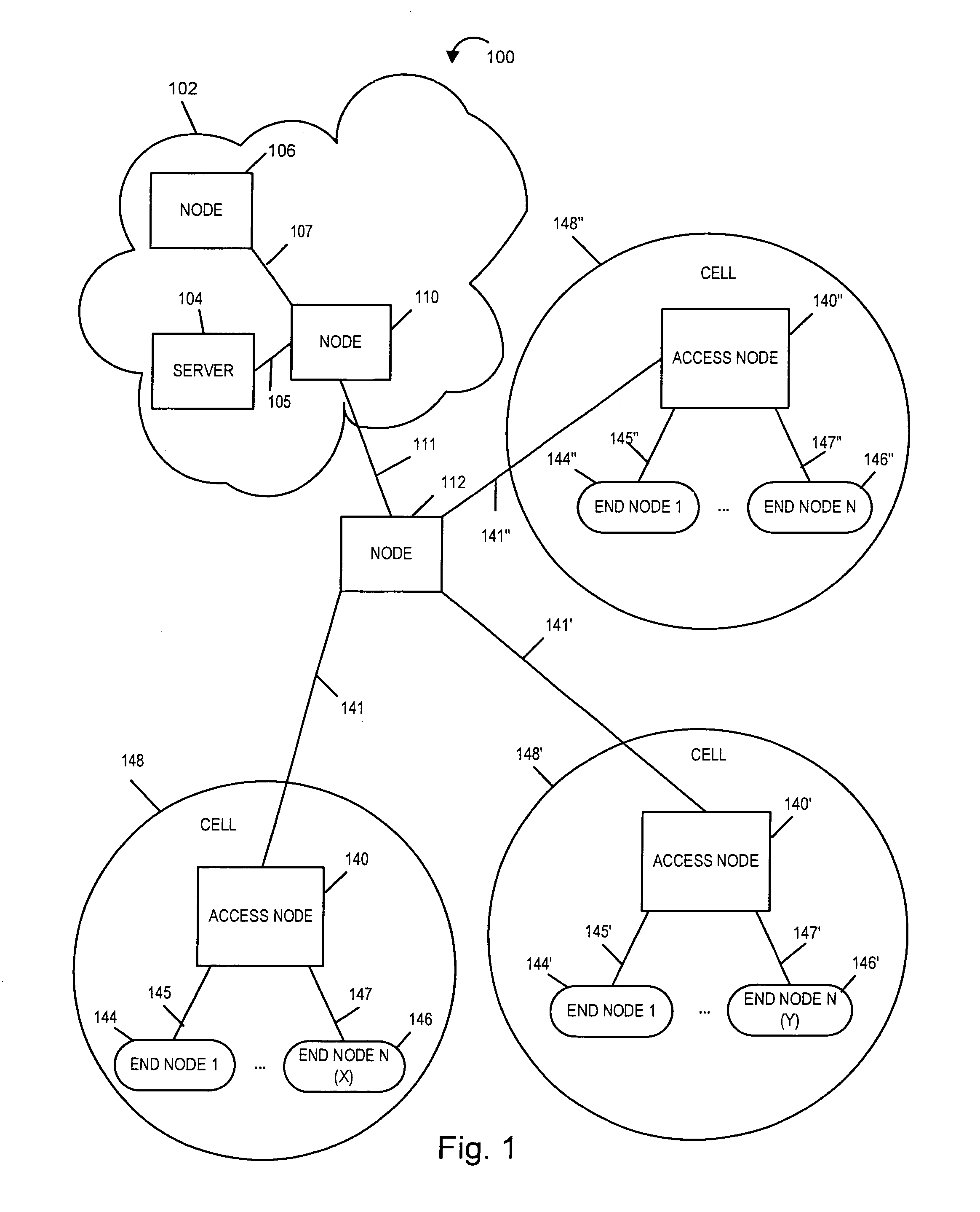
[0023]FIG. 1 illustrates an exemplary communication system 100 implemented in accordance with the present invention, e.g., a cellular communication network, which comprises a plurality of nodes interconnected by communications links. Exemplary communications system 100 is, e.g., a multiple access spread spectrum orthogonal frequency division multiplexing (OFDM) wireless communications sy...


PUM


Abstract

Methods and apparatus for using end nodes, e.g., wireless terminals, to discover base stations and communicate information about discovered access nodes, e.g., base stations, to other access nodes in a system are described. As the wireless terminal roams in the system and new access nodes are encountered, one or more physically adjacent access nodes will be informed of the presence of the new access node as a result of communications with the wireless terminal. A message indicating an access node's inability to route a message to another access node which is known to a wireless terminal may trigger the wireless terminal to begin the process of updating access node routing and neighbor information.

Description

FIELD OF THE INVENTION[0001]This invention relates to communications system and, more particularly, to methods and apparatus for routing messages based on physical layer information in wireless, e.g., cellular, communications networks.BACKGROUND OF INVENTION[0002]The Open System Interconnection (OSI) reference model is useful in explaining various communications and routing operations. The OSI reference model includes 7 layers with the application layer being the top most layer and the Physical Layer being the lowest layer. The physical layer is the layer which deals with actual physical connections and attributes of the physical connections in the system. Above the physical layer is a Data Link layer, sometimes referred to as the link layer. The link layer (Layer 2 in the OSI model) is sometimes described as a technology specific transfer layer. Above the link layer is the network layer (OSI Layer 3) where network routing and relaying is supported. The network layer is sometimes re...

Claims


Application Information

Patent Timeline
Patent Type & Authority Patents(United States)
IPC IPC(8): H04W40/00H04W8/00H04L12/751H04L12/703H04L12/24H04L47/76H04L45/02H04L45/28
CPCH04W8/005H04L45/02H04L45/28H04L41/069H04W8/00H04W40/24
Inventor LAROIA, RAJIVANIGSTEIN, PABLOMAZIK, DAVID R.PARIZHSKY, VLADIMIRPARK, VINCENTSRINIVASAN, MURARITSIRTSIS, GEORGE
Owner QUALCOMM INC
Why Eureka
Try Eureka