Printing control apparatus and printing control method

a control apparatus and control method technology, applied in printing mechanisms, spacing mechanisms, printing, etc., can solve the problems of inability to say that the deviation of the landing position of dots cannot stand out, the difficulty of individual determination whether or not dots are applied in the continuous region, and the difficulty of deviation to stand out. to achieve the effect of shortening the printing tim

Active Publication Date: 2015-11-10
SEIKO EPSON CORP
View PDF2 Cites 0 Cited by
  • Summary
  • Abstract
  • Description
  • Claims
  • Application Information

AI Technical Summary

Benefits of technology

[0013]In contrast to this, deviations are prevented from standing out due to the regions which are printed only on the outward path and the regions which are printed only on the return path alternating with each other as if split an even number of times since printing is carried out while each of the split regions is filled in on the outward path and the return path when splitting the regions an odd number of times.
[0030]According to the present invention, it is possible to provide a printing control apparatus and a printing control method where it is possible for landing position deviations to not stand out and for printing time to be shorter even when carrying out split printing.

Problems solved by technology

For example, it is difficult for deviations to stand out if dots are applied only in two pixels which interpose a boundary.
There are often circumstances where deviations in landing positions of dots cannot be said to stand out in circumstances where two pixels line up.
The region in the vicinity of the boundary is continuous in the width direction (main scanning direction) of the printing medium and it is complex to individually determine whether or not there is data where there dots are applied in the continuous region.

Method used


Image

  • Printing control apparatus and printing control method
  • Printing control apparatus and printing control method
  • Printing control apparatus and printing control method

Examples


Embodiment Construction

[0044]An embodiment of the present invention will be described below based on the diagrams.

[0045](1) Outline Explanation of Apparatus Configuration

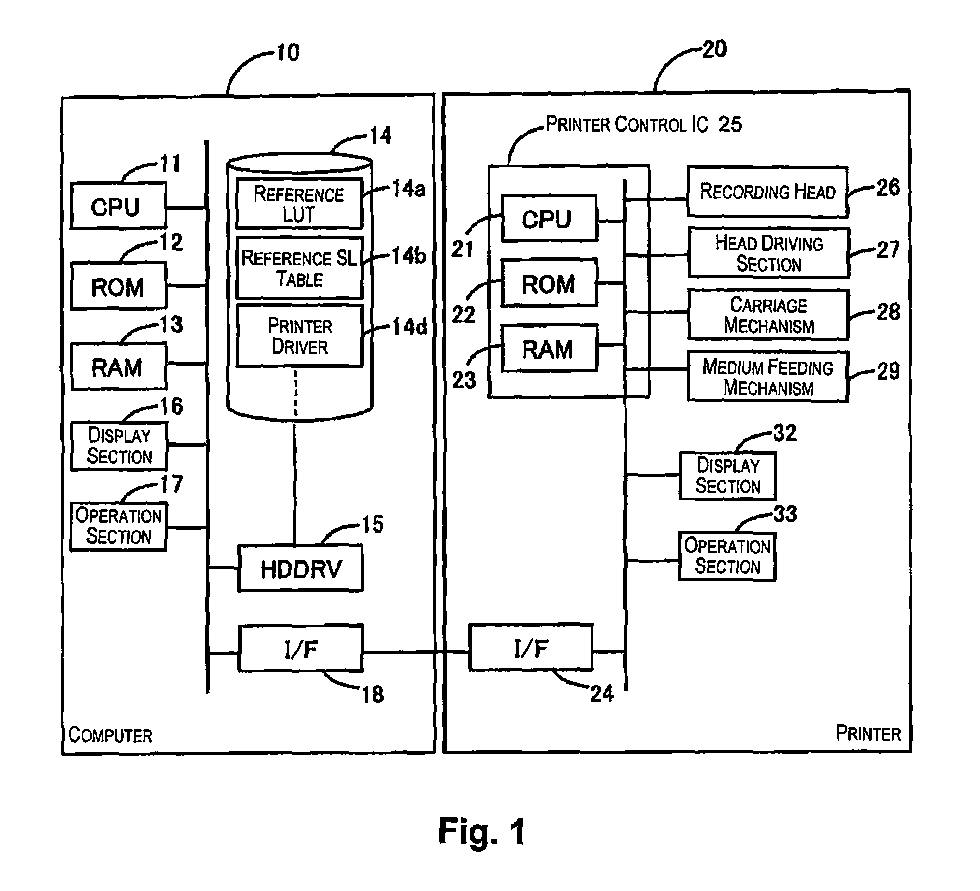
[0046]FIG. 1 illustrates a printing control apparatus according to an embodiment of the present invention using a block diagram.

[0047]The present system has, for example, a computer 10 and a printer 20. The computer 10 and / or the printer 20 are equivalent to an example of the printing control apparatus of the present invention. The printing control apparatus is the agent in executing a printing control method. In the computer 10, a CPU 11, which is the center for computation processing, controls the entirety of the computer 10 via a system bus. The bus is connected to a ROM 12, a RAM 13, and various types of interfaces (such as an I / F 18) and is also connected to a hard disk (HD) 14, which is a storage means, via a hard disk drive (HDDRV) 15. An operating system, an application program, a printer driver 14d, and the like are stored on the...


PUM


Abstract

A printing control apparatus includes a split printing control section configured to split a region that is printable in one band into a plurality of regions according to a predetermined number of splits, and configured to carry out interlace printing in each of split regions on an outward path and a return path. The split printing control section is further configured to determine whether there is data where dots are applied in a region in a vicinity of a boundary of two of the split regions, which includes at least one of the two of the split regions that are adjacent to each other, based on printing data for each of the split regions, and configured to carry out printing by making the number of splits an odd number of times in a case where there is data where dots are applied.

Description

CROSS-REFERENCE TO RELATED APPLICATIONS[0001]This application claims priority to Japanese Patent Application No. 2014-049494 filed on Mar. 12, 2014. The entire disclosure of Japanese Patent Application No. 2014-049494 is hereby incorporated herein by reference.BACKGROUND[0002]1. Technical Field[0003]The present invention relates to a printing control apparatus and a printing control method where split printing is carried out with a width of one band.[0004]2. Related Art[0005]There is disclosed a technique for split printing where printing is carried out by a plurality of times of scanning (multipass scanning) irrespective of printing being theoretically possible in one pass. As disclosed in JP-A-2006-326939 (PTL 1), an amount of ink flow is reduced by increasing the number of passes in multipass scanning when the remaining amount of ink is less than a threshold.SUMMARY[0006]As disclosed in PTL 1, there is a possibility that the normal number of passes in multipass scanning will incr...

Claims


Application Information

Patent Timeline
Patent Type & Authority Patents(United States)
IPC IPC(8): B41J2/205B41J29/38
CPCB41J29/38B41J2/2054B41J2/2132B41J19/145
Inventor KOBAYASHI, TAKASHISUDO, NAOKI
Owner SEIKO EPSON CORP
Why Eureka
Try Eureka