Multi-directional rotational mount

a multi-directional, rotating technology, applied in the direction of stands/trestles, camera body details, instruments, etc., can solve the problems of sacrificing safety to change the camera direction, requiring time and effort to adjust, manipulate, reposition, and re-align existing mounting systems,

Inactive Publication Date: 2016-01-05
SWIVIT
View PDF3 Cites 23 Cited by
  • Summary
  • Abstract
  • Description
  • Claims
  • Application Information

AI Technical Summary

Benefits of technology

[0010]Thus, the inventive system can be used in a configuration where the multidirectional camera mount can be coupled base on one side and a camera on the opposite side. The multidirectional mount will allow the rotation of the camera in a full 360 degrees, with n degrees of separation between specified stopping positions

Problems solved by technology

Previous means of changing the direction of a camera to different angles of footage required a complex adjustment of connectors and/or mounting mechanisms.
This req

Method used


Image

  • Multi-directional rotational mount
  • Multi-directional rotational mount
  • Multi-directional rotational mount

Examples


Embodiment Construction

[0034]Before explaining at least one embodiment of the invention in detail, it is to be understood that the invention is not limited in its application to the details of construction and to the arrangements of the components set forth in the following description or illustrated in the drawings. The invention is capable of other embodiments and of being practiced and carried out in various ways. For example, the inventive multidirectional mount can be used with ¼″ universal threaded adapters used on most cameras, tripods and the quick release mount. Also, it is to be understood that the phraseology and terminology employed herein are for the purpose of description and should not be regarded as limiting.

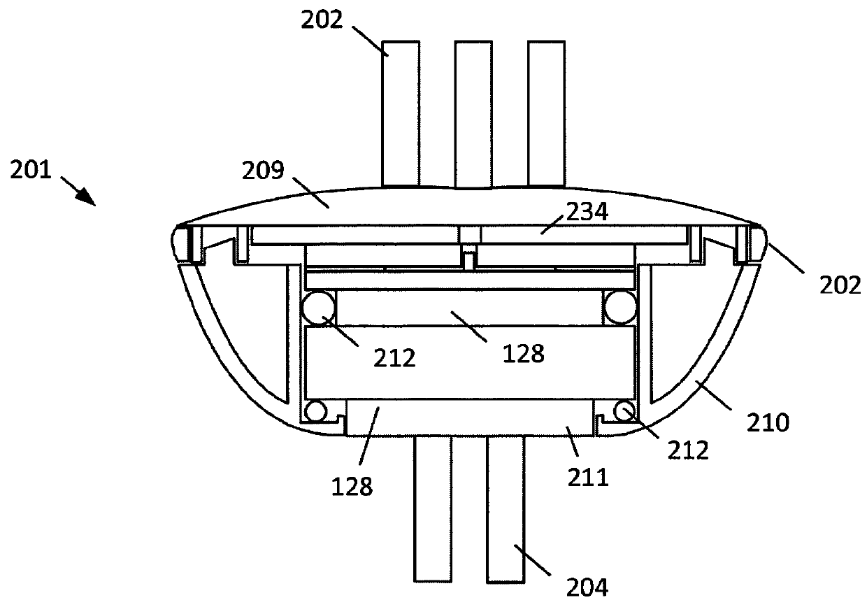
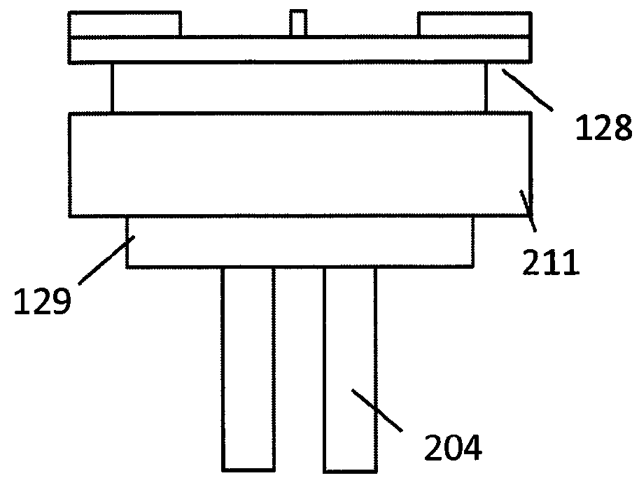
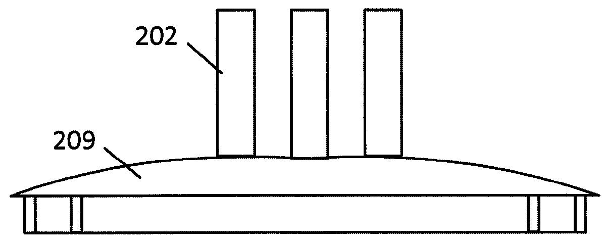
[0035]An embodiment of the present invention is illustrated in the FIGS. 1 and 2. FIG. 1 illustrates a cross sectional view of an embodiment of a multidirectional rotational mount 201 and FIG. 2 illustrates an exploded view of an embodiment of a multidirectional rotational mount. In th...


PUM


Abstract

A multidirectional camera mount allows quick, easy and safe rotational adjustment of camera orientation and/or position. An upper side of the multidirectional camera mount can include upper mounting tabs attached to a camera, camera housing or other device. A lower side of the multidirectional camera mount can include lower mounting tabs which can be affixed to various objects, while static or during numerous physical activities. The multidirectional camera mount can allow the upper mounting tabs to rotate relative to the lower mounting tabs.

Description

CROSS-REFERENCE TO RELATED APPLICATIONS[0001]This application claims priority to U.S. Provisional Application No. 61 / 977,614, “Multidirectional Camera Mount Allowing Quick, Easy And Safe Adjustment Of Camera Direction To Film More Of The Environment Around The Camera And User” filed on Apr. 9, 2014, which is hereby incorporated by reference in its entirety.TECHNICAL FIELD[0002]The disclosed invention can be used in the technical field of still camera and video camera mounting systems. More specifically, the disclosed invention can be used with still cameras and video cameras mounting systems having improved functionality with rotational capabilities to various positions.BACKGROUND[0003]Many individuals have found it desirable to record their activities, hobbies, events, and film productions. Conventionally, cameras are mounted in a fixed position, allowing only a certain field of view of any one direction at a time. Problems with many conventional camera mount systems is that they l...

Claims


Application Information

Patent Timeline
IPC IPC(8): G03B17/00G03B17/56G03B17/08
CPCG03B17/561G03B17/08F16M13/04F16M11/08F16M11/10F16M11/2064F16M2200/024
Inventor MORLON, JASON, Y
Owner SWIVIT
Why Eureka
Try Eureka