

Modular bus system
- Summary
- Abstract
- Description
- Claims
- Application Information
AI Technical Summary
Benefits of technology
Problems solved by technology
Method used
Image

Examples
Embodiment Construction
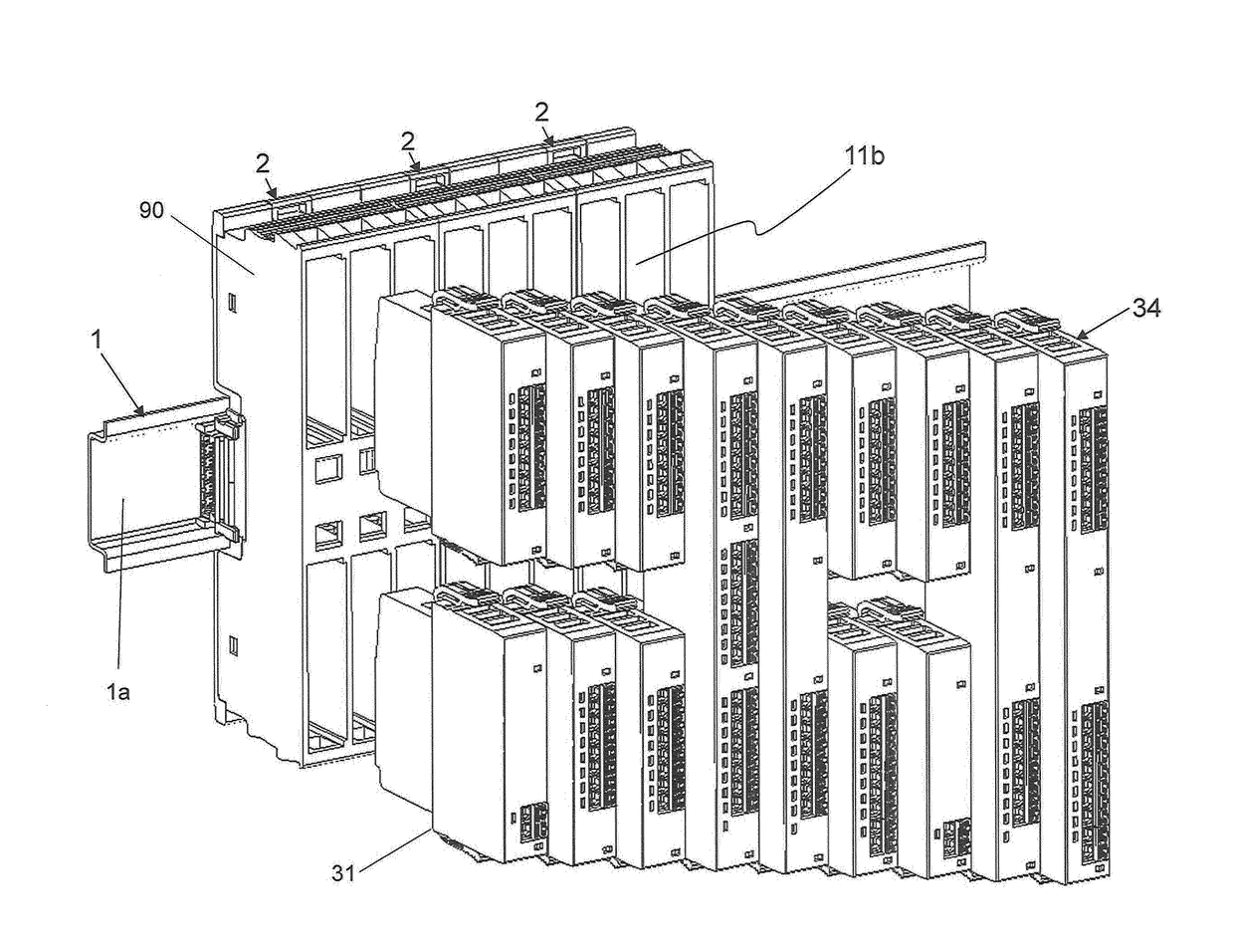
[0039]FIG. 1 shows a portion of an exemplary modular bus system 100 with three decoupled base modules 2, which are mounted spaced from one another on a support rail 1, preferably plugged to the support rail 1. It should already be noted at this point that for proper operation the base modules 2 are electrically connected to each other, and optionally mechanically as well, as shown in FIG. 8 or 9, for example.
[0040]The geometrical alignment of the base modules 2 and their components with respect to the support rail 1 can be explained most easily with the aid of a 3D coordinate system with axes x, y, and z, wherein in FIG. 1 the longitudinal axis of the support rail 1 coincides with the x-axis. Support rail 1 has a base 1a which extends in the x-direction in the view chosen in FIG. 1, and which is located in a plane spanned by the x- and z-axes. It should be noted at this point that the support rail 1 is arranged in the same plane in FIGS. 8, 9, 11, 13, and 14. Only in FIGS. 10 and 12...
PUM
 Abstract
Description
Claims
Application Information