Seal Apparatus for a Ship Propeller Shaft and Method of Making the Apparatus

a technology of propeller shaft and sealing apparatus, which is applied in the direction of vessel construction, application, and propulsive elements, can solve the problems of long out-of-service time of the ship in a service dock, demanding and time-intensive boring operation, etc., and achieves the reduction of the number of bored holes or passages, the effect of reducing the number of holes or passages

Active Publication Date: 2014-11-27
BLOHM VOSS IND
View PDF2 Cites 10 Cited by
  • Summary
  • Abstract
  • Description
  • Claims
  • Application Information

AI Technical Summary

Benefits of technology

[0007]In view of the above it is an object of an embodiment of the invention to provide a seal apparatus for sealing around a rotating shaft, such as a propeller shaft, of a watercraft between the exterior water and an interior lubricant space, which provides a simplified, robust and effective supply and/or return of a fluid to one or more seal chambers of the seal apparatus, while avoiding or minimizing the disadvantages of the prior art as set forth herein. For example, an embodiment of the inventive apparatus aims to minimize or reduce the number of bored holes or passages that must penetrate through the ship's hull or housing of the shaft and/or the seal arrangement, to achieve a more compact arrangement, and to achieve a more-rapid and more-econom

Problems solved by technology

These sections of the fluid supply and return lines guided through the housing are typically individual bored holes, that each respectively correspond to a single fluid supply or return line, and that each require a technically demanding and time intensive boring operation for their formation.
This is especially problematic and disadvantageous when a seal arrangement of an existing ship propeller

Method used


Image

  • Seal Apparatus for a Ship Propeller Shaft and Method of Making the Apparatus
  • Seal Apparatus for a Ship Propeller Shaft and Method of Making the Apparatus
  • Seal Apparatus for a Ship Propeller Shaft and Method of Making the Apparatus

Examples


Embodiment Construction

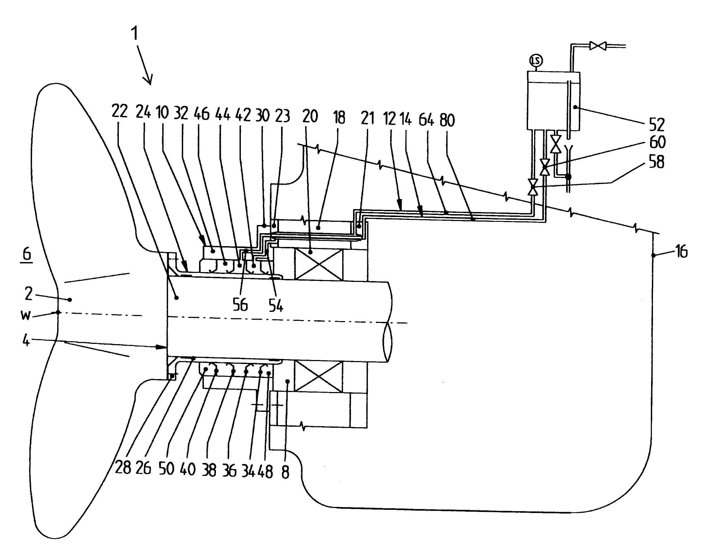
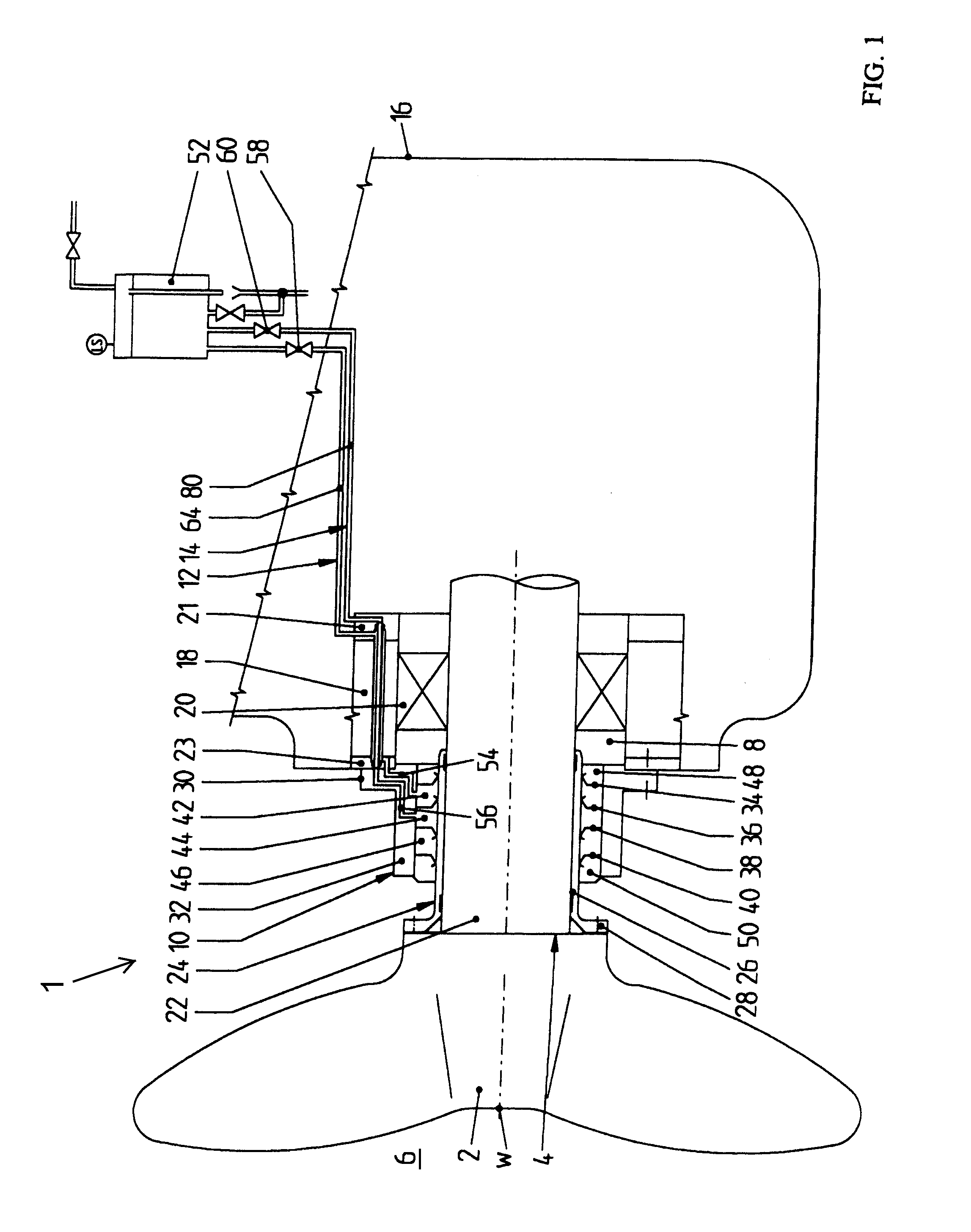
[0021]A seal apparatus 1 according to the invention is for providing a seal around a rotating shaft 4 of a watercraft, where the shaft passes outwardly through a hull 16 of the watercraft from a hull interior side to a hull exterior side below the water line outside the hull of the watercraft. The “watercraft” can be any ship, boat, submarine, etc. that has a hull operating under, in and / or on the water. The rotating shaft may for example be a propeller shaft that drives a main propulsion propeller of the watercraft, or may drive an impeller of a water jet propulsion system, or may drive a propeller or impeller mounted on a gondola or pod housing of a pod drive system, or for a transverse thruster or any other thruster device such as an active rudder thruster. As further alternatives, a seal apparatus 1 according to the invention can be provided for any other type of rotating shaft penetrating out through the hull, not limited to a shaft driving a propeller or impeller.

[0022]FIG. 1 ...


PUM

PropertyMeasurementUnit
Diameteraaaaaaaaaa

Abstract

A seal apparatus, for sealing around a rotating shaft such as a propeller shaft of a watercraft between the exterior water and an interior lubricant space, includes a multiple seal arrangement with plural seal rings forming seal chambers therebetween, and plural fluid medium lines supplying and/or returning a respective fluid medium to a respective seal chamber. A section of a first medium line is formed as an axial passage through a housing of the apparatus, and a section of a second medium line is formed by a pipe arranged within the axial passage in the housing. A method of making such an apparatus especially by retrofitting an existing seal arrangement involves inserting a pipe into an axial passage in the housing in order to establish two medium lines through the housing where there was previously only one medium line.

Description

PRIORITY CLAIM[0001]This application is based on and claims the priority under 35 USC 119 of German Patent Application DE 10 2013 008 967.0, filed on May 22, 2013, the entire disclosure of which is incorporated herein by reference.FIELD OF THE INVENTION[0002]The invention relates to a seal apparatus for sealing a rotating shaft such as a propeller shaft of a watercraft between an exterior water side and an interior side in a lubricant space. The invention further relates to a method of making such a seal apparatus.BACKGROUND INFORMATION[0003]Various types and configurations of seal arrangements, bushings, packing boxes, stuffing boxes, glands and the like are known for providing a seal around the rotating shaft that drives a ship's propeller, for example where the shaft penetrates through the stern of the ship from the interior to the exterior of the ship's hull. The seal arrangement must effectively prevent water from the exterior environment, i.e. from the exterior of the hull bel...

Claims


Application Information

Patent Timeline
IPC IPC(8): B63H23/32
CPCB63H2023/327B63H23/321F16J15/004Y10T29/49716
Inventor RUSCH, MATHIASBRAND, JOERGWRAGE, MARKOBOETTCHER, NILS
Owner BLOHM VOSS IND
Why Eureka
Try Eureka