Position reference sensor

a technology of reference sensor and position sensor, which is applied in the direction of distance measurement, instruments, and using reradiation, etc., can solve the problems of unwanted reflection moving relative to the object, reflection disappearing, and problem of discrimination, so as to reduce the identification threshold, avoid false results, and optimize discrimination

Inactive Publication Date: 2018-01-11
GUIDANCE MARINE
View PDF5 Cites 10 Cited by
  • Summary
  • Abstract
  • Description
  • Claims
  • Application Information

AI Technical Summary

Benefits of technology

[0010]An advantage of the fact that the light source is configured to emit light having a first component and a second component, that the processor is configured to determine a distance between the position reference sensor and a target based on the emitted light and the detected reflected light, and that the processor is configured to determine that the target is a selective retroreflector based on the intensity of the first component of the light in the detected reflected light and the intensity of the second component of the light in the detected reflected light means that the position reference sensor is able to identify reflections that have come from a selective retroreflector and distinguish them from unwanted reflections. Measuring the distance between a position reference sensor and a selective retroreflector which may be fixed to an object is likely to provide a more reliable and stable indication of the distance between the position reference sensor and the object than measuring the distance between a position reference sensor and an unwanted reflection on the object, because the unwanted reflection may move relative to the object or the unwanted reflection may not be viewable over a wide-range of angles. The fact that the position reference sensor is able to identify reflections that have come from a selective retroreflector and distinguish them from unwanted reflections may eliminate the need for user intervention to identify a suitable retroreflective target.
[0139]The method may further comprise combining the first and second components of light into a single beam and controlling the size and / or divergence of the single beam. This provides a straightforward, and high performance, means to control the size and divergence of the single beam, for example, to collimate the single beam so that is does not spread too wide before reaching a target. Alternatively, the method may comprise controlling the size and / or divergence of the first and second components of the light before the first and second components of the light are combined into a single beam, which provides a more compact optical arrangement.

Problems solved by technology

However, problems can occur when the laser pulse is reflected from reflective surfaces or elements on the object other than the retroreflective target.
A problem is that the unwanted reflection is unlikely to provide a stable and strong reflection which would provide a reliable retroreflective target, for example, the unwanted reflection may not be visible over a wide range of viewing angles, so if the position of the vessel relative to the object changes, the reflection may disappear.
Additionally, the unwanted reflection may move relative to the object, for example, if the unwanted reflection came from retroreflective tape or markings on a crane, or a high-visibility jacket worn by a rig worker.
However, asking for user confirmation is inconvenient and time consuming, and may be prone to error.

Method used


Image

  • Position reference sensor
  • Position reference sensor
  • Position reference sensor

Examples


Embodiment Construction

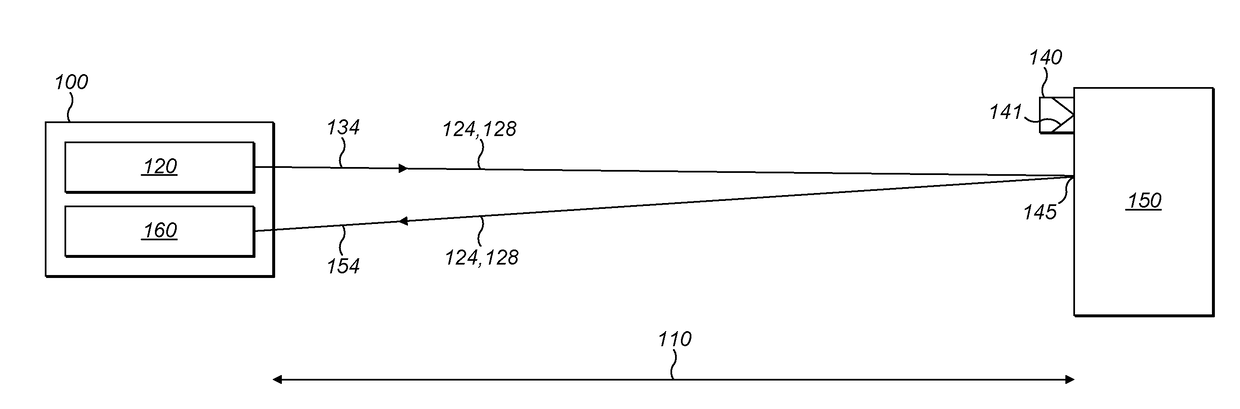
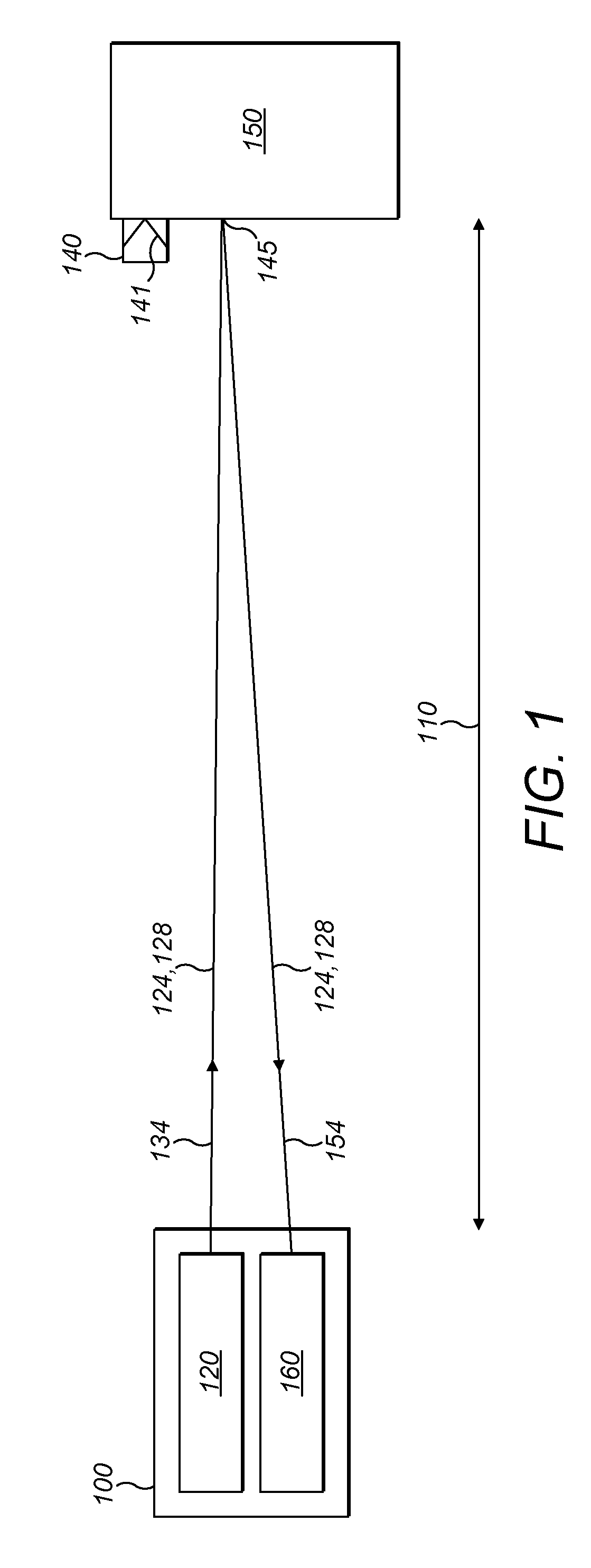
[0159]FIG. 1 shows a position reference sensor 100 being used to determine a distance 110 between the position reference sensor 100 and a point 145 on object 150.

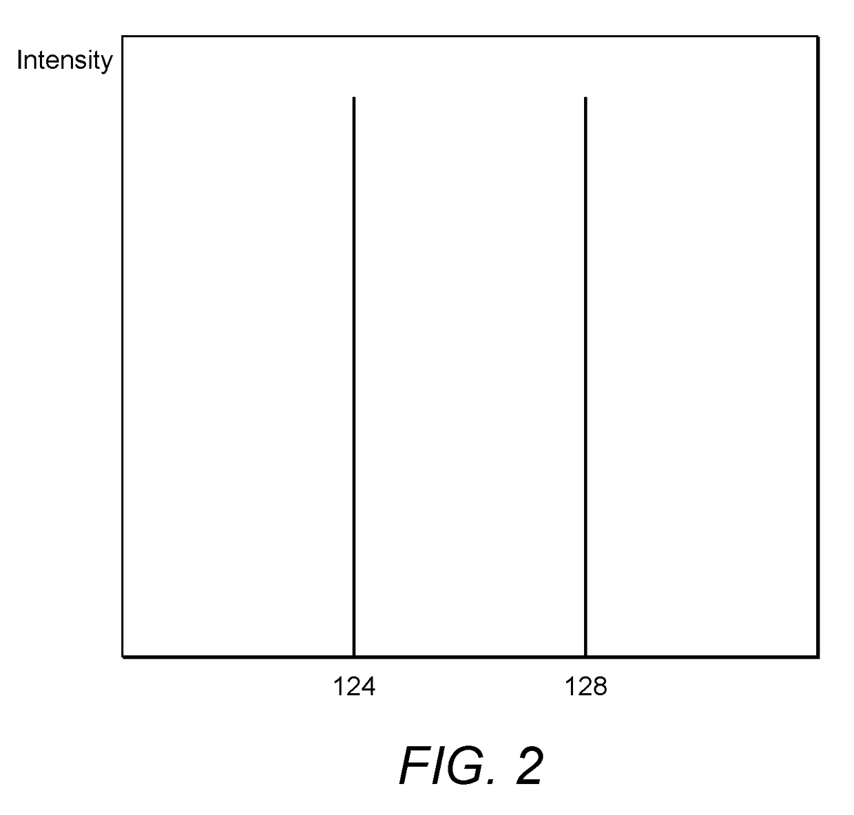
[0160]The position reference sensor 100 has a light source 120 which emits a beam of light 134 containing light at two different wavelengths—a first wavelength 124 and a second wavelength 128.

[0161]The beam 134 is directed towards the object 150. A selective retroreflector 140 is attached to the object 150. The selective retroreflector 140 has dielectric mirrors 141 which have been chosen to reflect the first wavelength 124 but not the second wavelength 128.

[0162]As well as the selective retroreflector 140, the object 150 has a variety of other reflective surfaces or elements (such as point 145) which can lead to an unwanted reflection 154 which does not come from the selective retroreflector 140. The unwanted reflection 154 is not a good choice for the position reference sensor 100 to use for determining the distance to th...


PUM


Abstract

A position reference sensor (100) has a light source (120), a detector (160) and a processor (170). The light source (120) is configured to emit light having a first component and a second component. The detector (160) is configured to detect reflected light. The processor (170) is configured to determine a distance between the position reference sensor (100) and a target based on the emitted light and the detected reflected light. The processor (170) is also configured to determine that the target is a selective retroreflector (140) based on the intensity of the first component of the light in the detected reflected light and the intensity of the second component of the light in the detected reflected light.

Description

FIELD OF THE INVENTION[0001]The present invention relates to a position reference sensor, for example, a position reference sensor for use in marine applications for determining the position of a vessel relative to an object. The present invention also relates to a position reference system.BACKGROUND OF THE INVENTION[0002]Position reference sensors are used to determine position information indicating the position of a vessel relative to another object, such as another vessel or a fixed or floating platform, like an oil rig. Position information from a position reference sensor can be used by a dynamic positioning system to control the position of the vessel relative to the object. The dynamic positioning system may, for example, maintain a fixed relative position between the vessel and the object without the need for a physical connection between the vessel and the object to provide a virtual tether, for example, in a cable laying convoy. Alternatively, the dynamic positioning sys...

Claims


Application Information

Patent Timeline
Patent Type & Authority Applications(United States)
IPC IPC(8): G01S7/486G01S7/499G01S7/481G01S17/10G01J1/44G01S7/4861
CPCG01S7/4861G01S7/4817G01S17/10G01S7/499G01J1/44G01S17/42G01S17/74G01S17/88B63B43/18G01B11/14G01C3/02G01S7/4808G01S7/484G01S17/08
Inventor MILES, RUSSELLMCKNIGHT, DAVID
Owner GUIDANCE MARINE
Why Eureka
Try Eureka