Structure for christmas light

a technology for structures and lights, applied in the direction of semiconductor devices for light sources, coupling device connections, lighting and heating apparatus, etc., can solve the problems of pin bending, corrosion and/or erosion, complicated assembly process, etc., and achieve the effect of easy assembly

Inactive Publication Date: 2010-10-07
LIU CHUN MING
View PDF3 Cites 14 Cited by
  • Summary
  • Abstract
  • Description
  • Claims
  • Application Information

AI Technical Summary

Benefits of technology

[0005]The primary object of the present invention is to provide a structure for LED Christmas light, which is easy to assemble and maintain strong holds between components after assembly so that the light bulb and the electrodes can be in firm contact.
[0007]The main feature of the structure for LED Christmas light of the present invention includes a plurality of matching and unique designs of the components so that the components can be easily matched and elegantly engaged for correct assembly. The electrodes of the present invention are not the conventional plate electrodes. Instead, the present invention uses the flexible electrodes having more functionality. After assembling the light holder and the flexible electrodes, the LED light bulb can contact the flexible electrodes for electrical connection after inserted into the cavity, and no additional complicated means is required. A buckle structure is also included in the light bulb and the light cap of the present invention to prevent the light bulb from disengaging from the light holder. A shade can be formed on the end of the light cap to protect the light bulb from damage and to enhance the decorative function of the LED light bulb.

Problems solved by technology

The assembly process is complicated and may damage the coated (electroplating or electroless plating or vacuum coating) thin film when bending the pins, which may lead to the corrosion and / or erosion and electrical leakage.
Furthermore, the pins are bended many times during the manufacturing and testing, and are prone to break.
The safety and reliability of the products are both easily compromised.

Method used


Image

  • Structure for christmas light
  • Structure for christmas light
  • Structure for christmas light

Examples


Embodiment Construction

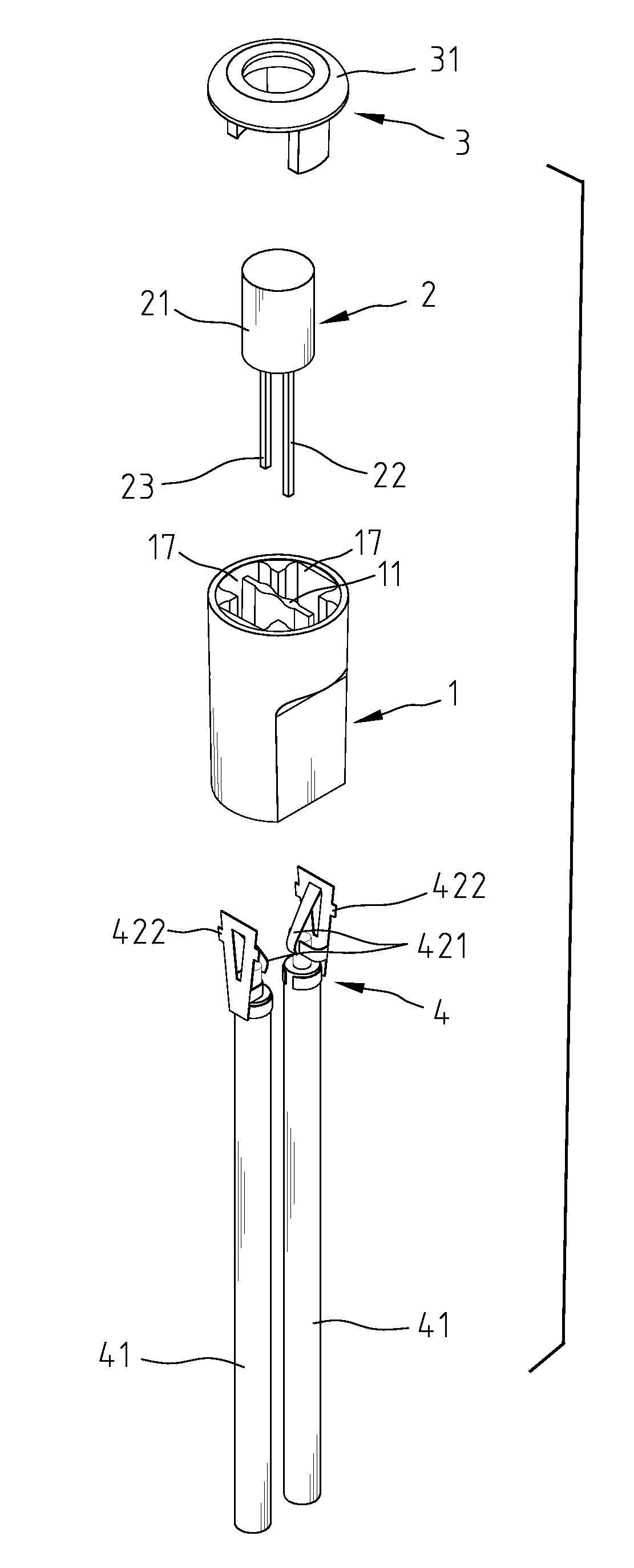
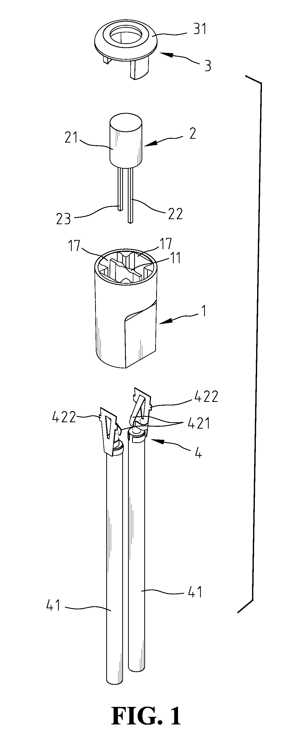
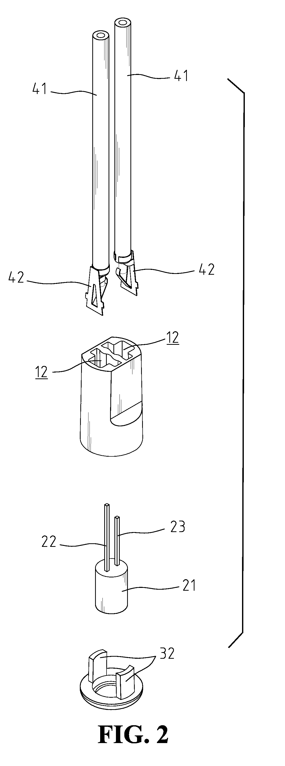
[0023]FIGS. 1-3 show two schematic views of the present invention from different angles and a top view of the light holder, respectively. The structure for LED Christmas light of the present invention includes a light holder 1, an LED light bulb 2, a light cap 3 and two wire sets 4.

[0024]Light holder 1 is a hollow cone body that is wide at the top and narrow at the bottom, and has a skeltonized top and a skeletonized bottom. The center of light holder 1 includes a thin plate-shaped separating part 11 connected to inner wall 17 of light holder 1 to divide the hollow interior of light holder 1 into two cavities 12. Each of the two opposite sides of inner wall 17 of light holder 1 connected to separating part 11 forms a slot 13 extending downwards from the top. Each of the two opposite sides of inner wall 17 of light holder 1 facing separating part 11 includes a lock trench extending downwards from the top. Because the upper part of light holder 1 is round, slot 13 and lock trench 14 b...


PUM


Abstract

A structure for LED Christmas light is provided, including a light holder, being a hollow body having a separating part connected to the inner wall of the light holder to divide the hollow interior of the light holder into two cavities. Each of the two opposite sides of the inner wall of the light holder connected to the separating part forms a slot and face the surface of the separating part of the two cavities, with each having a guiding channel. Two wire sets are fixed inside the two cavities. An LED light bulb has a positive pin and a negative pin inserted inside the guiding channel, respectively, and being electrically connected to the wire sets. A light cap has a holding part passing the LED light bulb to tightly engage to the top of the light holder so as to fix the LED light bulb to the light holder.

Description

FIELD OF THE INVENTION[0001]The present invention generally relates to a structure for Christmas light, and more specifically to a structure for Christmas light using light-emitting diode (LED), easy to assemble and having sturdy hold after assembly.BACKGROUND OF THE INVENTION[0002]Because the tungsten light bulb consumes more electric energy and results in secondary environment contamination, light-emitting diode (LED) becomes a promising unit and an attractive alternative for illumination, especially as Christmas lights. The Christmas lights are usually hanged on Christmas trees and constantly lighted, therefore, it is necessary to build a structure with lower power consumption, longer life span and light in weight. LED provides an excellent option.[0003]As the LED Christmas light is small in size, the connection between the components must be simplified to make the assembly easy. A conventional LED Christmas light includes an LED light bulb, light base for buckling the LED light ...

Claims


Application Information

Patent Timeline
Patent Type & Authority Applications(United States)
IPC IPC(8): H01R33/00
CPCF21V19/0005H01R33/09F21Y2101/02F21Y2115/10
Inventor LIU, CHUN-MINGCHEN, UEI-SHINLIU, CHIH-WEI
Owner LIU CHUN MING
Why Eureka
Try Eureka