

Syndrome tables for decoding turbo-product codes
a technology of turbo-product codes and syndrome tables, which is applied in the direction of code conversion, coding, electrical equipment, etc., can solve the problem of significant overhead for accessing this huge amount of data from the data memory buffer
- Summary
- Abstract
- Description
- Claims
- Application Information
AI Technical Summary
Benefits of technology
Problems solved by technology
Method used
Image

Examples
first embodiment
[0035]FIG. 3 is a diagram illustrating a TPC decoder. TPC decoder 304 shows one embodiment of a system which performs the process of FIG. 1. For clarity, components which are not directly related to the steps recited in FIG. 1 are not shown herein. For example, a write controller corresponding to read controller 302 and a TPC encoder corresponding to TPC decoder 304 are not shown. In some embodiments, read controller 302 (which includes TPC decoder 304) is implemented on a semiconductor device, such as an application-specific integrated circuit (ASIC) or field-programmable gate array (FPGA). In some such embodiments, storage 300 comprises another semiconductor device.
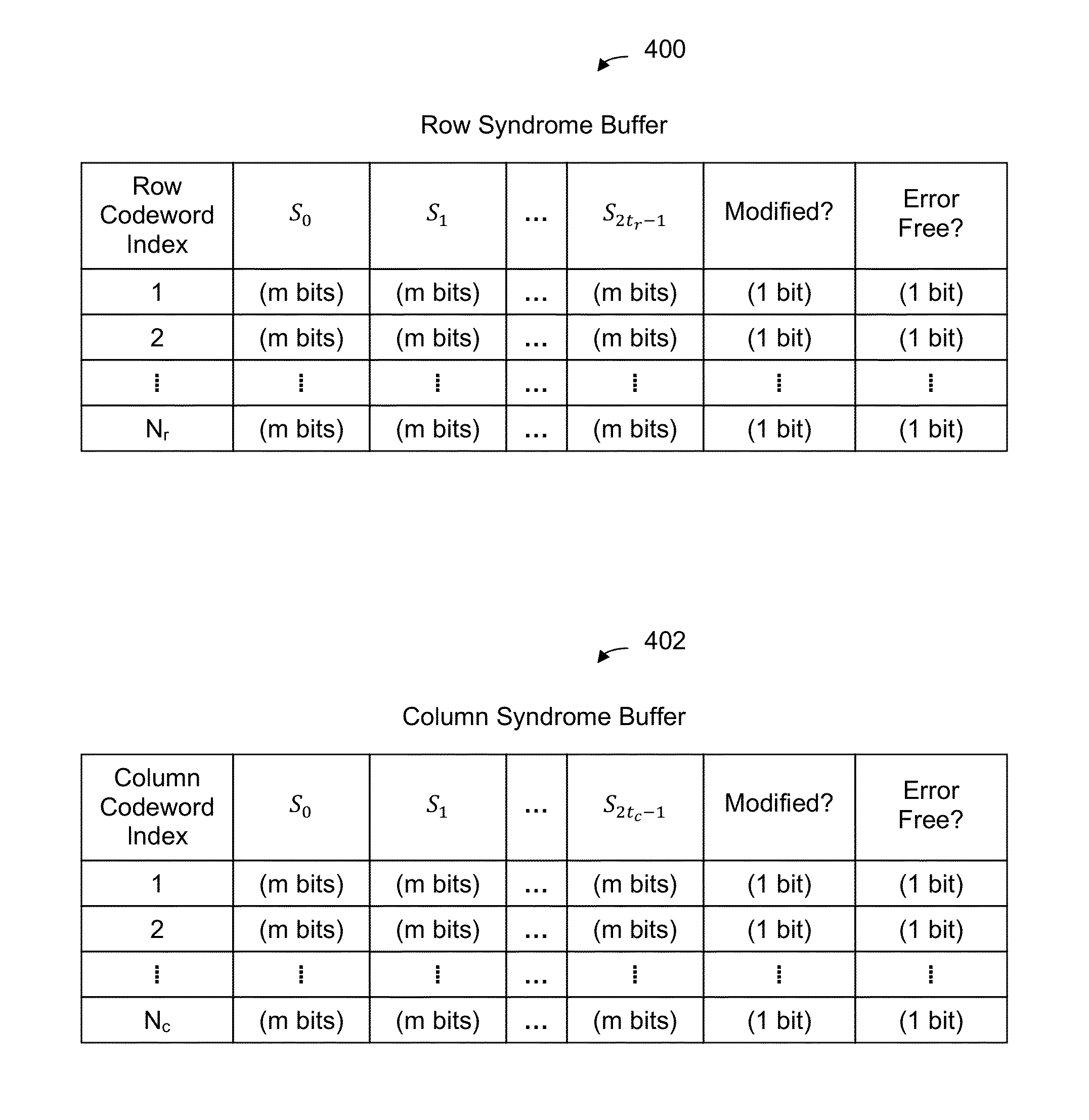
[0036]TPC codewords are stored on storage 300 (e.g., stored there by a write controller, not shown). In some embodiments, storage 300 comprises solid state storage, such as NAND Flash. During some initialization process, TPC codewords are retrieved from storage 300 and row syndrome buffer 310 and column syndrome buffer ...
second embodiment
[0133]Returning to FIG. 3, a TPC decoder may include other components in addition to or as an alternative to those shown in FIG. 3. The following figure shows a TPC decoder with more components.
[0134]FIG. 13 is a diagram illustrating a second embodiment of a TPC decoder. As described above, the exemplary TPC decoder may be implemented as a semiconductor device, such as an ASIC or FPGA. To preserve readability, storage 300 and read controller 302 shown in FIG. 3 are not shown in this figure.
[0135]In the example shown, initializing block 1300 is responsible for initializing the TPC decoder when decoding of a new TPC codeword begins. Initial row syndromes and initial column syndromes are generated for and saved to row syndrome buffer 1302 and column syndrome buffer 1304, respectively. For those row codewords or column codewords where the corresponding syndromes are all 0s, the error free bit is set to 1 by initializing block 1300. If not, the error free bit is set to 0 by initializing ...
PUM
 Abstract
Description
Claims
Application Information