Suture delivery system

a delivery system and suction tube technology, applied in the field of surgical instruments, can solve the problems of increasing the cost of device production, prior art devices suffer from several drawbacks, etc., and achieve the effect of quick and accura

Active Publication Date: 2016-08-23
SOTIRAS HLDG LLC
View PDF17 Cites 1 Cited by
  • Summary
  • Abstract
  • Description
  • Claims
  • Application Information

AI Technical Summary

Benefits of technology

[0008]One aspect of the invention generally pertains to a suture delivery system that provides quick

Problems solved by technology

However, these prior art devices suffer from several drawbacks.
First, the nature of these devices requires that they be constructed of a metallic

Method used


Image

  • Suture delivery system
  • Suture delivery system
  • Suture delivery system

Examples


Embodiment Construction

[0021]In the following detailed description numerous specific details are set forth in order to provide a thorough understanding of the invention. However, it will be understood by those skilled in the art that the present invention may be practiced without these specific details. For example, the invention is not limited in scope to the particular type of industry application depicted in the figures. In other instances, well-known methods, procedures, and components have not been described in detail so as not to obscure the present invention.

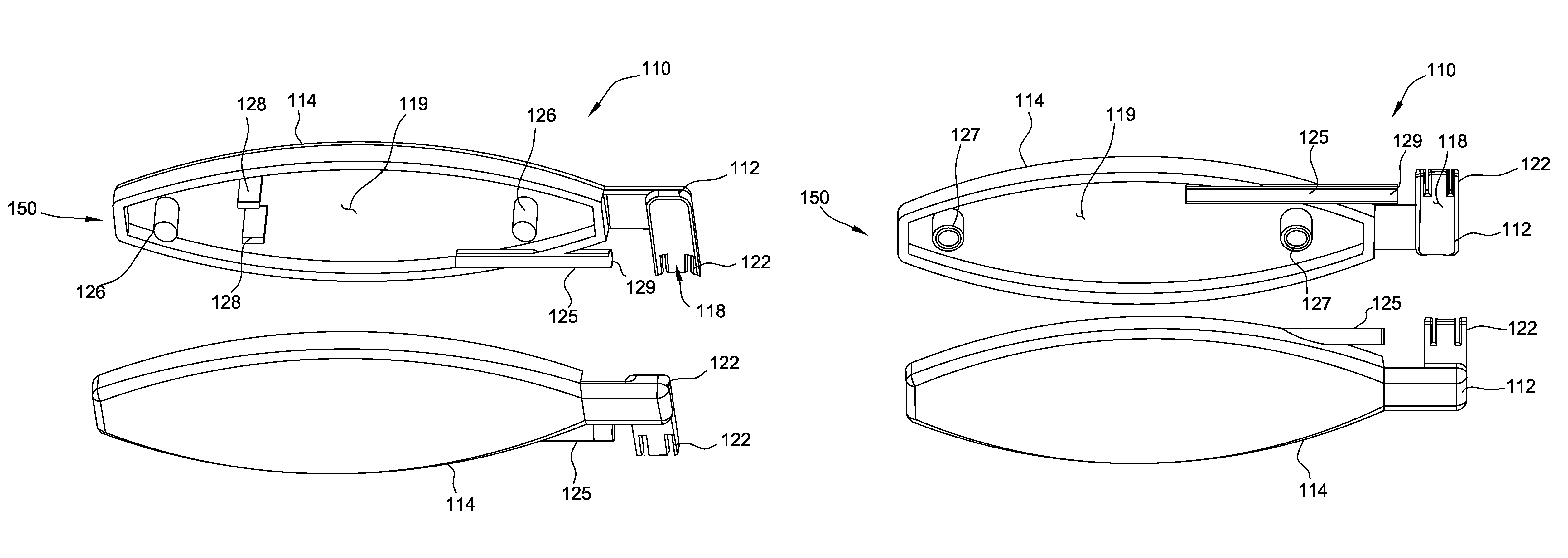
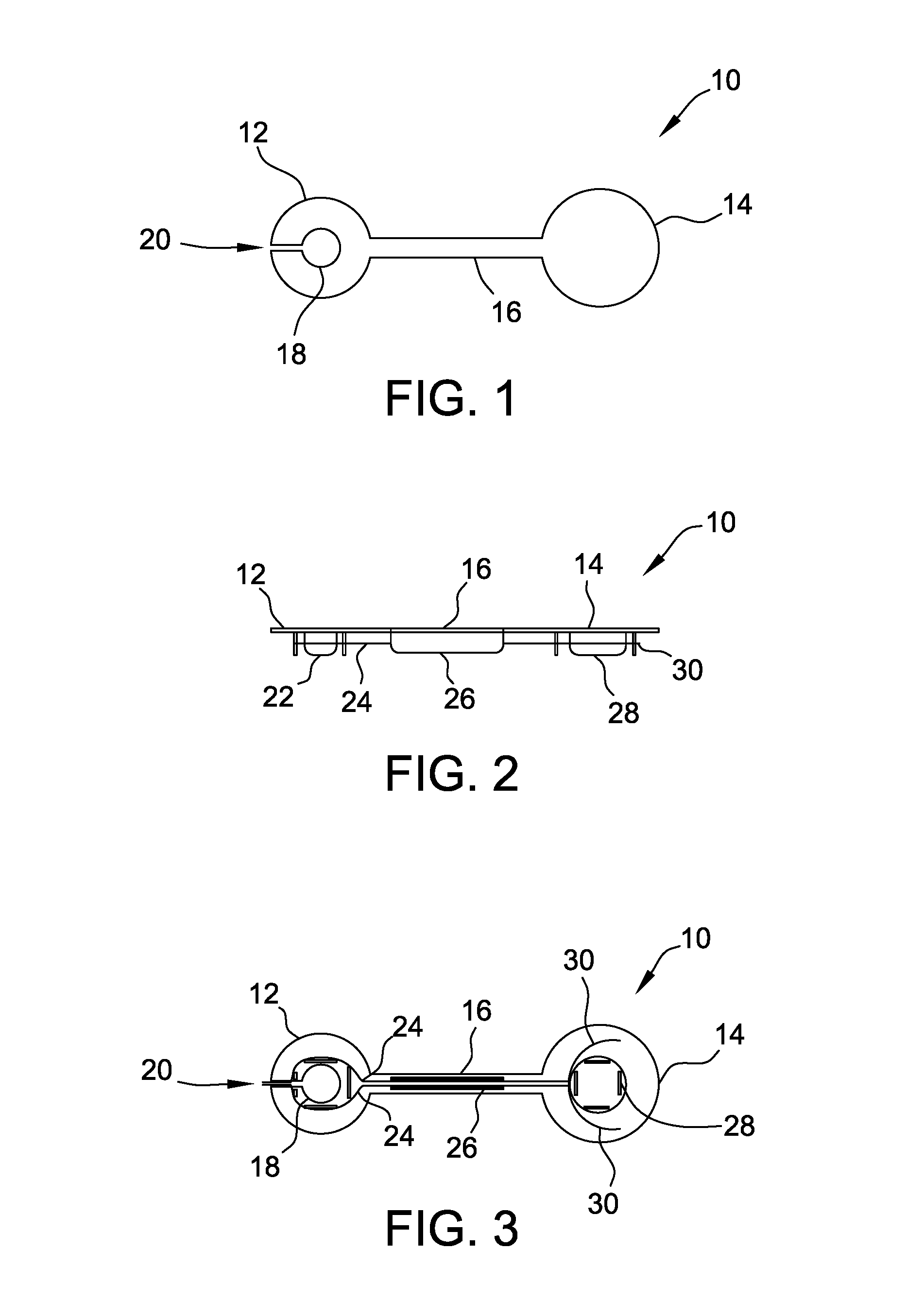
[0022]FIGS. 1-3 illustrate a suture delivery system according to an embodiment of the present invention. The system includes a base 10. In the illustrated embodiment, the base 10 is provided with a roughly hourglass shape composed of a distal 12 portion and a body portion that is formed by a proximal 14 portion and an extended handle portion 16. Distal portion 12, alternately referenced as a suture loop snare, is advantageously provided with a ...


PUM


Abstract

A suture delivery system includes a distal portion having a central opening therein and one or more flanges surrounding said central opening; a body portion connected with said distal portion; and at least one suture strand and needle combination removably connected with at least one of said distal portion and said body portion, wherein a first portion of said suture strand engages said flanges of said distal portion and said body portion stores a second portion of said suture strand and said needle.

Description

CROSS REFERENCES[0001]This application claims priority to U.S. Provisional Patent Application No. 61 / 539,774, filed Sep. 27, 2011.TECHNICAL FIELD OF THE INVENTION[0002]The present invention relates generally to surgical tools and, more particularly, to a device for enhancing the process of reconnecting soft tissue with underlying bone structures.BACKGROUND OF THE INVENTION[0003]Staples and orthopedic washers have been used for many years to surgical attach soft tissues to underlying bone structures. Prior art staples are metallic “U”-shaped structures wherein the legs of the staple are driven into the underlying bone structure to sandwich the soft tissue between a web that connects the legs of the staple and the underlying bone. Examples of such staples are described in U.S. Pat. Nos. 4,592,346 and 4,793,335.[0004]Prior art orthopedic washers are typically round or oval in shape with an open center and provided with multiple sharp pins as well as blunt posts on the underside of the ...

Claims


Application Information

Patent Timeline
IPC IPC(8): A61B17/04
CPCA61B17/06114A61B17/06133A61B17/0401A61B17/0466A61B2017/06142
Inventor RILEY, A. JAMIESCHMIDT, GARY J.PARANJPE, AMOD P.
Owner SOTIRAS HLDG LLC
Why Eureka
Try Eureka