
Vehicular display device
a technology of a display device and a display device, which is applied in the direction of optics, instruments, optical elements, etc., can solve the problems of inability to ensure a sufficient visibility, inability to visually recognize the display of virtual images, and inability so as to reduce the influence of external light, the effect of reducing the chance of viewpoint movement and sufficient visibility
- Summary
- Abstract
- Description
- Claims
- Application Information
AI Technical Summary
Benefits of technology
Problems solved by technology
Method used
Image

Examples
Embodiment Construction
[0027]Specific illustrative embodiments relating to a vehicular display device of the present invention will be now described with reference to the accompanying drawings.
[0028]
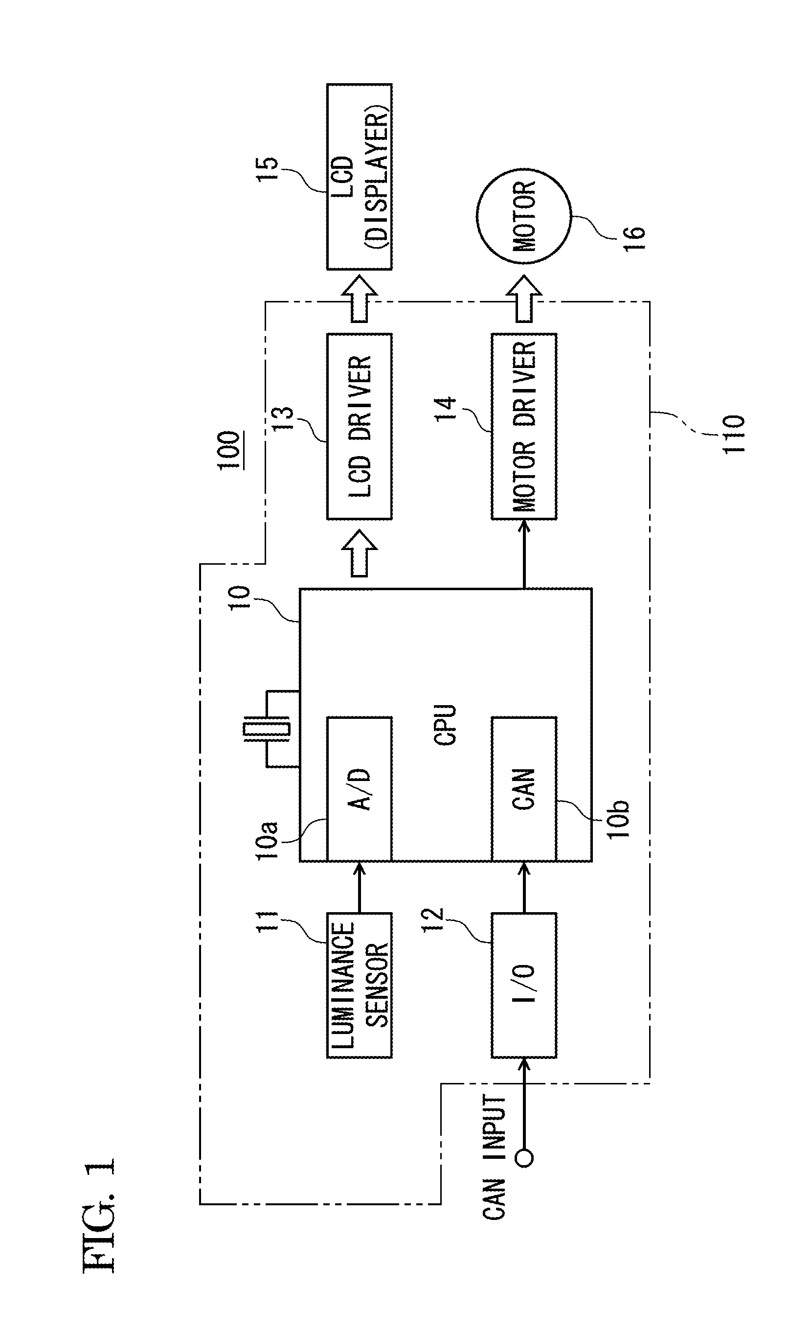
[0029]A configuration example of an electric circuit of a HUD (head-up display) device main body 100 according to the present embodiment is shown in FIG. 1. As shown in FIG. 1, the electric circuit of the HUD device main body 100 includes a control circuit 110, a liquid crystal displayer (LCD) 15 and an electric motor 16, and the liquid crystal displayer 15 and the electric motor 16 are connected to the control circuit 110.
[0030]The control circuit 110 includes a microcomputer (CPU) 10, an illuminance sensor 11, an input / output interface (I / O) 12, a LCD driver 13, and a motor driver 14.
[0031]The microcomputer 10 implements various functions required by the HUD device main body 100, by executing a pre-installed program. Also, the microcomputer 10 has an A / D conversion processing unit 10a and a CAN communication...
PUM
 Abstract
Description
Claims
Application Information