LED sign visibility enhancing device

a technology of enhanced device and led sign, which is applied in the field of illuminated signs, can solve the problems of wiring damage, expensive and time-consuming replacement of lamps and other services of such signs, and can burn lamps, etc., and achieve the effect of adequate visibility of the message and enhanced message visibility

Inactive Publication Date: 2007-02-27
AHMADI 50 YOSETTE J +1
View PDF8 Cites 10 Cited by
  • Summary
  • Abstract
  • Description
  • Claims
  • Application Information

AI Technical Summary

Benefits of technology

[0010]The applicant has found that the usual highway or roadway sign can be considerably improved through the use of prismatic materials in forming the message or as a background for opaque materials used for the message of such signs. Prismatic glass, acrylic plastic materials or other light-enhancing materials may be used to enhance the visibility of the message on the sign. A mirror or mirrors or other suitable reflecting surfaces within the sign will reflect ambient light coming through a transparent top and ends of the sign to provide adequate visibility of the message even in limited light.
[0011]When it becomes dark, such signs do require additional means to illuminate the message. Rather than connect the sign to an external power source, such as an electrical utility power grid, applicant has found that a self-contained lighting system containing a battery, a solar panel to charge the battery, an electrical circuit connected to the battery, and a few well-placed LEDs (light-emitting diodes) connected to the electrical circuit is adequate to keep the message on the sign visible throughout the darkness hours, while enhancing illumination during the day. A switching device may form part of the electrical circuit responds to the level of ambient light to switch the LEDs on and off. LEDs have been found to be highly reliable, long lasting, and are capable of supplying the level of illumination required.
[0013]a) provides only minimum interference with solar illumination through a top window;

Problems solved by technology

There are some disadvantages to such signs for highway or roadway use because lamps can burn out leaving the sign dark and, in many cases, illegible or illegible at a desired distance.
Replacing of lamps and other servicing of such signs is expensive and time consuming.
Dirt and dust are a problem and wiring can be damaged from heavy storms, hail, etc.
The amount of electrical energy consumed by such incandescent or fluorescent lamps is also a disadvantage.

Method used


Image

  • LED sign visibility enhancing device
  • LED sign visibility enhancing device
  • LED sign visibility enhancing device

Examples


Embodiment Construction

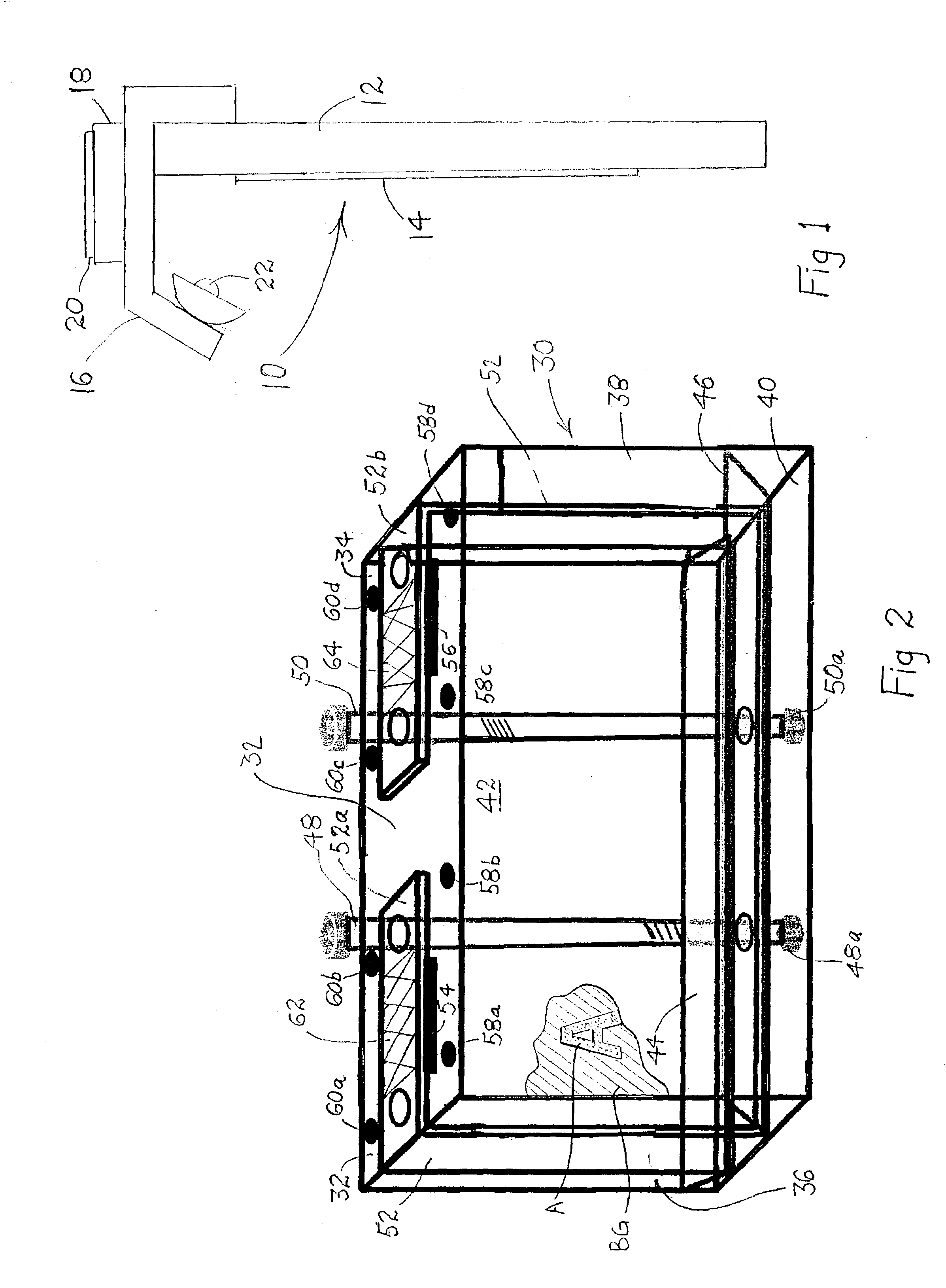
[0020]FIG. 1 is a side elevational view of a flat roadway sign, generally designated 10, including a face panel 12 carrying a message 14. Secured to panel 12 is a bracket 16 which carries an electrical assembly 18, including an electrical circuit CT and a solar panel 20. Electrically connected to electrical assembly 18 is a lamp consisting of one or more LEDs 22 with optional reflectors 22A.

[0021]Electrical assembly 18 includes connections to LED 22, a battery B showing in dashed lines within assembly 18, which is connected to be charged to solar panel 20, and a switching circuit SC responsive to the level of ambient light for powering the LEDs 22 on at the end of the day when ambient light is inadequate to see the message 14 and to turn it off in the morning.

[0022]During the pendency of the above-referenced Provisional Patent Application, I conceived of the application of this invention to box type internally or back lit signs, whereby such signs may be supported, employ ambient ba...


PUM


Abstract

A lighting system for a sign consists of a bracket to be attached to the top of a flat sign, the bracket including a surface supporting a battery, a solar battery charging cell and a circuit connecting the battery to an LED lamp directed to illuminate the message on the sign. A second embodiment includes a box-type sign with a housing having a light-transmitting top panel, a message on both side panels, light-transmitting ends, and either one or two mirrors supported on the bottom angled to reflect light against the messages. A support bracket includes straps extending part way across the top panel carrying solar panels, batteries, and a circuit are located under the straps and one or more LED lamps are connected to the circuit and arranged to be powered when the ambient light becomes too low to properly illuminate the message or messages.

Description

REFERENCE TO RELATED APPLICATION[0001]This Non-Provisional Patent Application claims benefit of U.S. Provisional Patent Application Ser. No. 60 / 358,022 filed Feb. 20, 2002, and hereby claims the benefit of the embodiments therein and of the filing date thereof.BACKGROUND OF THE INVENTION[0002]There are many types and varieties of illuminated signs, some of which have translucent panels with an opaque message with a background which is illuminated by lamps from behind. Others are just opposite wherein light from lamps on the inside shine through transparent or translucent letters or numerals. Some are painted signs illuminated from the front from above or below. One common type of sign is referred to as a box sign because it is in the form of a box with lamps, either inside or on the outside directed toward a front panel carrying its message. Some such signs may carry a message on both sides.[0003]There are some disadvantages to such signs for highway or roadway use because lamps can...

Claims


Application Information

Patent Timeline
Patent Type & Authority Patents(United States)
IPC IPC(8): G09F13/04
CPCG09F13/02G09F27/007G09F13/04
Inventor AHMADI, WILLIAM Y.
Owner AHMADI 50 YOSETTE J
Why Eureka
Try Eureka