Fluid ejection apparatus

a technology of ejection apparatus and ejection port, which is applied in the direction of fluid jet surgical cutter, moving spraying apparatus, spray nozzle, etc., can solve the problems of difficult to bring the ejection port close to an accurate position of the operation site, operation site, and negative pressure on the suction port, so as to achieve sufficient visibility of the operation site

Inactive Publication Date: 2011-04-21
SEIKO EPSON CORP
View PDF6 Cites 11 Cited by
  • Summary
  • Abstract
  • Description
  • Claims
  • Application Information

AI Technical Summary

Benefits of technology

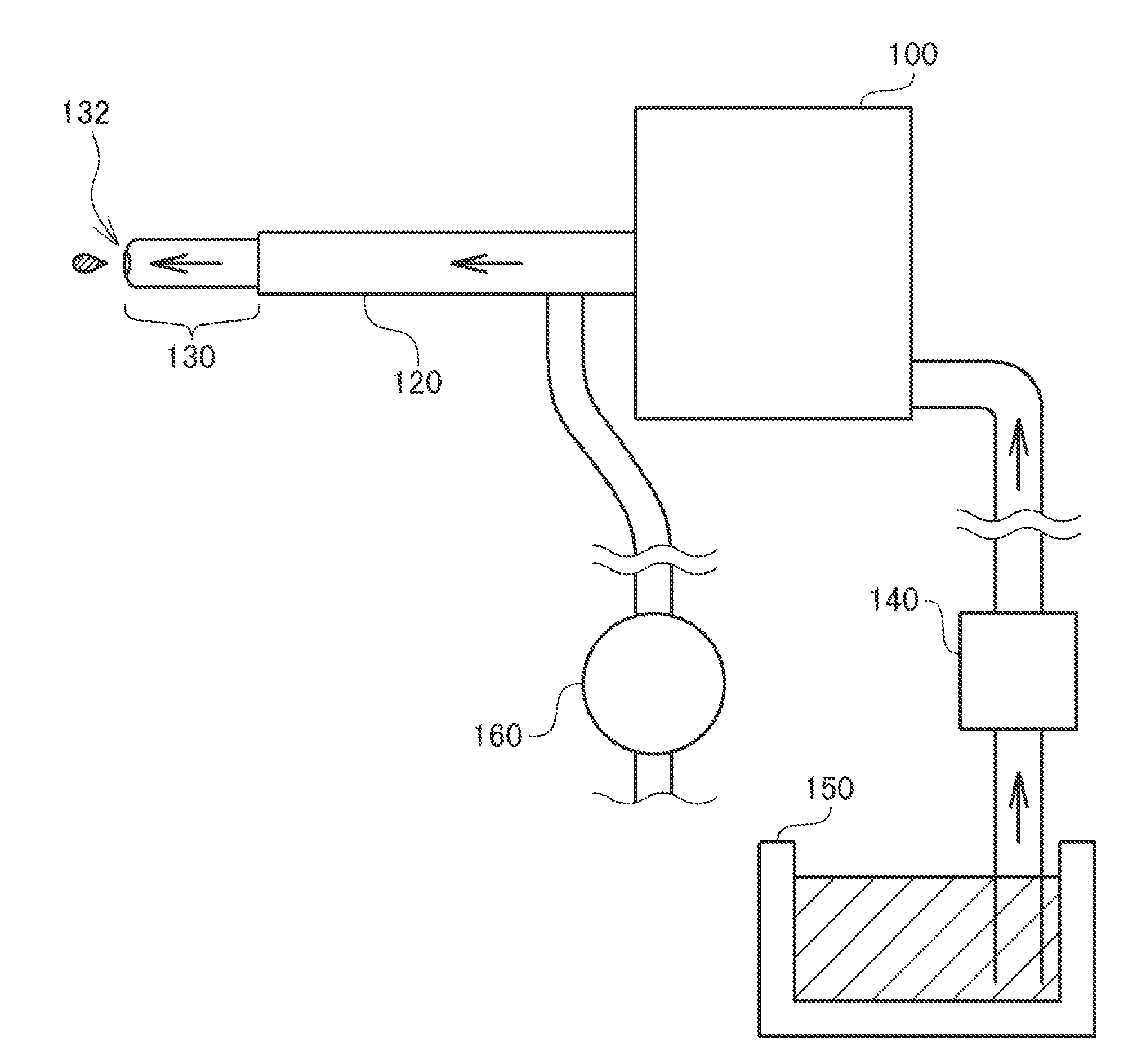
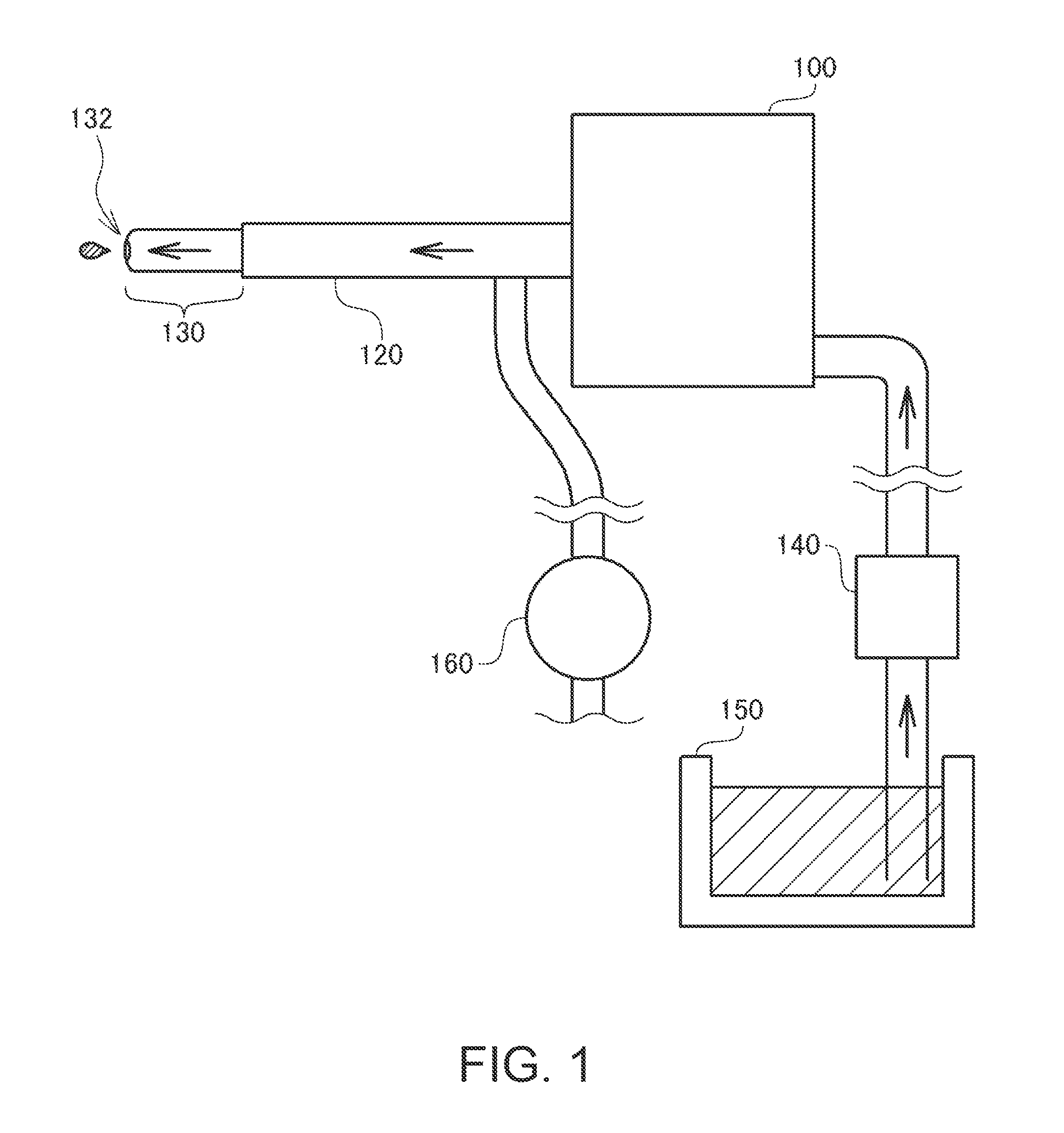
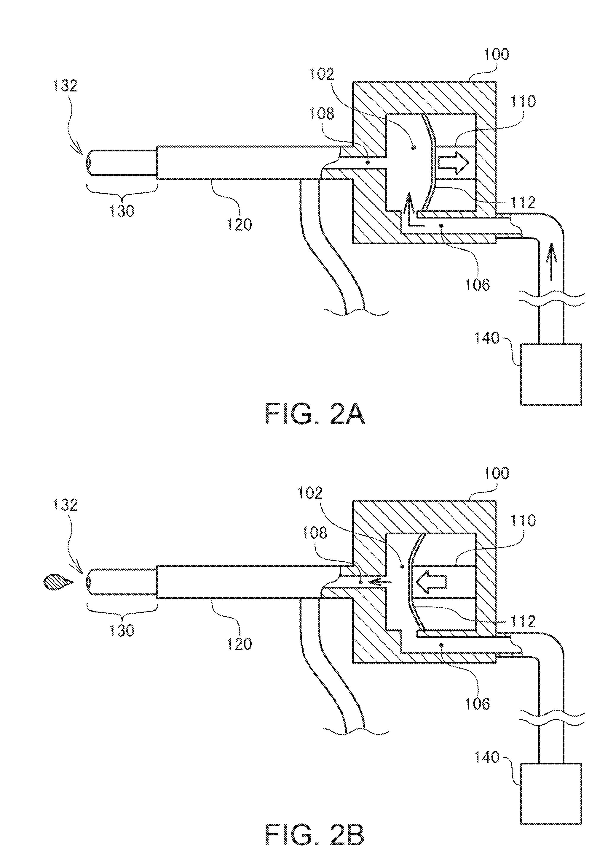
[0025]The expression “eject the fluid in a pulsed manner” means that the fluid is ejected in association with variations in flow rate or flow velocity of the ejected fluid. This mode of ejecting the fluid in a pulsed manner includes an intermittent ejection in which the fluid is ejected while repeating ejection and stop. However, what is essential is just that the flow rate and the flow velocity of the fluid are varied, and hence it does not necessarily have to be the intermittent ejection. When the fluid is ejected in a pulsed manner as described above, the fluid is ejected while varying the flow rate or the flow velocity of the fluid. Therefore, the total amount of the fluid to be ejected can be restricted to a small amount in comparison with the case where the fluid is ejected at a constant flow rate (or at a constant flow speed). In this configuration, the fluid to be accumulated in the vicinity of the ejection port can be restricted to a smaller amount. Therefore, the visibility of the operation site can be secured sufficiently by moving the fluid to the suction port and removing the same.

Problems solved by technology

As a matter of fact, if the ejected fluid or blood flowing out at the time of incision is accumulated in the periphery of the operation site, the surgeon can hardly view the operation site, and hence it becomes difficult to bring the ejection port close to an accurate position of the operation site.
However, with the proposed technology, a negative pressure at the suction port is exerted also to the operation site.
Consequently, there arise problems such that the operation site is displaced due to the negative pressure, or the operation site may be sucked into the suction port and hence become damaged.
If the suction port is provided at a position far from the ejection port so as to prevent the negative pressure from being exerted to the operation site, the fluid in the periphery of the ejection port or blood can hardly be sucked, and hence the visibility in the periphery of the ejection port can hardly be secured.

Method used


Image

  • Fluid ejection apparatus
  • Fluid ejection apparatus
  • Fluid ejection apparatus

Examples


first modification

C-1. First Modification

[0062]In the embodiment described above, the groove portions 134 are described to be provided on a side surface of the nozzle portion 130 (see FIGS. 4A and 4B). However, the groove portions may be provided on the end surface of the nozzle portion 130 in addition to the side surface thereof.

[0063]FIG. 6 is an explanatory drawing of the nozzle portion in a modification in which a groove portion is provided also on an end surface thereof viewed from the direction of the end surface of the nozzle portion. As illustrated, the nozzle portion 130 in the modification is provided with thin end surface grooves 136 on the end surface where the ejection port 132 is provided, and the end surface grooves 136 are connected to the groove portions 134 provided on the side surface of the nozzle portion 130. When the ejection port 132 is brought toward the operation site, the end surface of the nozzle portion 130 is located at a position closest to the operation site (see FIG. 5...

second modification

C-2. Second Modification

[0064]The fluid ejection apparatus in the embodiment described above has been described such that the groove portions 134 are provided in the periphery of the nozzle portion 130, and the fluid is moved to the suction port 164 by the groove portions 134. However, it is also possible to provide a number of brushes in the periphery of the nozzle portion 130 to move the fluid toward the suction port 164 through flow channels formed between the brushes.

[0065]FIGS. 7A and 7B are explanatory drawings showing a nozzle portion according to a modification in which fluid is moved using a flow channel between brushes provided in the periphery of the nozzle portion. As illustrated in FIG. 7A, the nozzle portion 130 in the modification is provided with a number of the brushes 138 in the periphery of the nozzle portion 130. When viewing in the direction indicated by a hollow arrow in FIG. 7A, the brushes 138 surround the ejection port 132 (see FIG. 7B). As indicated in FIG....


PUM


Abstract

A fluid ejection apparatus ejecting fluid from an ejection port, includes: a suction port provided at a position apart from the ejection port and applied with a negative pressure; and a fluid channel provided between the vicinity of the ejection port and the suction port, and configured to suck the fluid in the vicinity of the ejection port by the surface tension of the fluid and move the same toward the suction port.

Description

BACKGROUND[0001]1. Technical Field[0002]The present invention relates to a technology configured to eject fluid from an ejection port.[0003]2. Related Art[0004]In recent years, a surgical method for incising an operation site or excising foreign substances such as thrombus or tumor by means of a pressure of the fluid by pressurizing fluid such as water or physiological saline and ejecting the same to the operation site during the surgical operation is developed. In a fluid ejection apparatus used in the surgical operation as described above is configured to eject the fluid from an ejection port provided at an extremity of a nozzle. At the time of the surgical operation, a surgeon holds the nozzle, directs the ejection port to the operation site, and causes fluid to be ejected from the ejection port, whereby incision of the operation site or excision of the tumor or the like is achieved.[0005]At the time of the surgical operation, it is important to eject the fluid exactly to the ope...

Claims


Application Information

Patent Timeline
Patent Type & Authority Applications(United States)
IPC IPC(8): B05B1/08
CPCB05B9/01B05B15/0406A61B17/3203B05B17/0607B05B15/0425B05B14/00B05B14/30
Inventor KOJIMA, HIDEKISUGIMURA, SHIGEOMATSUZAKI, TAKAHIRO
Owner SEIKO EPSON CORP
Why Eureka
Try Eureka