Floor mat

Inactive Publication Date: 2009-05-21
SANRITZ CORP
View PDF4 Cites 12 Cited by
  • Summary
  • Abstract
  • Description
  • Claims
  • Application Information

AI Technical Summary

Benefits of technology

[0004]Present invention can solve the problems by providing sufficient visibility with conventional room lights or foot lamps of

Problems solved by technology

Disadvantageously, however, such a room light cannot provide sufficient light around passenger's feet.
Similarly, a foot lamp that is specially designed for lighting up passenger's feet is usually mounted to shine down,

Method used


Image

  • Floor mat
  • Floor mat
  • Floor mat

Examples


Example

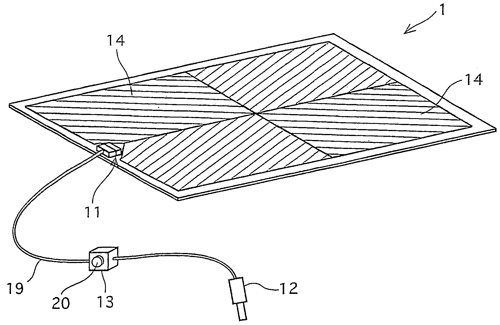
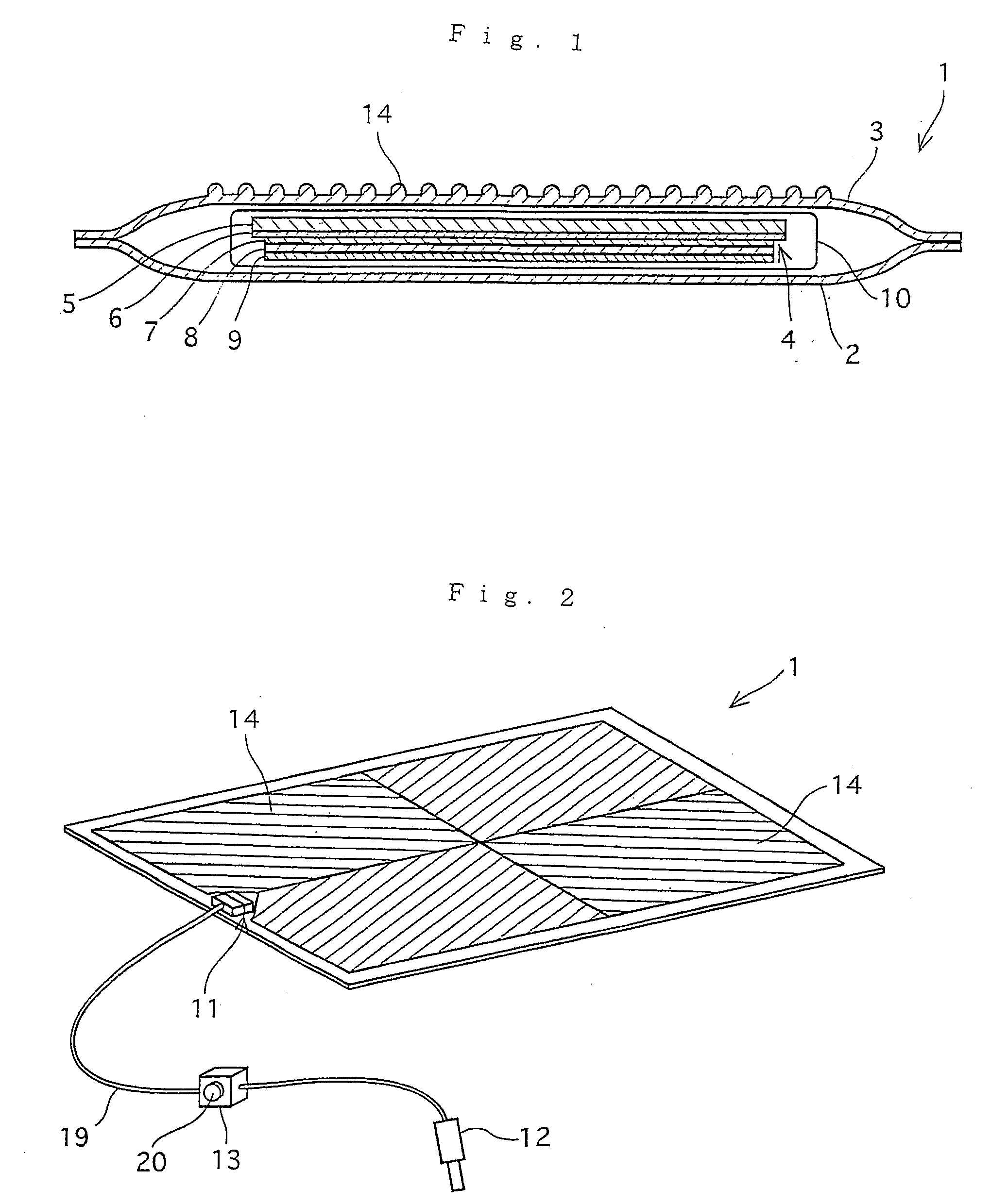
[0011]FIG. 1 shows a cross sectional view of a floor mat according to the present invention. The floor mat 1 is formed with an electro luminescent body 4 placed between a lower sheet 2 and an upper sheet 3. The lower sheet 2 has flexibility and its base surface is provided with non-slip finishing. The upper sheet 3 is made of a transparent or semi-transparent material having flexibility and elasticity with many projecting lines 14 formed on its surface. The projecting lines 14, formed as a part of the upper sheet 3 with the same material, are the parallel lines each shaped of semi-cylinder.

[0012]The electro luminescent body 4 comprises a film 5 made of PET (polyethylene terephthalate) that is laminated with a transparent electrode 6 e.g. ITO(indium tin oxide), a luminescent layer 7, an insulating layer 8, and a backside electrode 9 in this order.

[0013]The luminescent layer 7 is either a dispersion type which is formed with powdered luminescent materials mixed in a high dielectric bi...


PUM


Abstract

A conventional room lamp or foot lamp has a problem that the place where user's feet are is difficult to see and poor in visibility, and on the other hand, when the lamp is made unnecessarily bright to cause luminance distribution in the field of view to be discontinuous, an unpleasant phenomenon called glare occurs. A surface EL light emitting body is entirely coated with a transparent waterproof sheet and then it is sandwiched and bonded between upper and lower sheets to form on mat. At least a part of the upper sheet is formed transparent, a lead wire is fixed to the EL light emitting body, and a connector to be connected to a power supply outlet in a vehicle is provided at the forward end of the lead wire. A light control circuit for altering the emission intensity of the EL light emitting body and a circuit for automatically turning off the power upon disconnection of the lead wire are provided in the middle of the lead wire, and the EL light emitting body is made to emit light at a luminance of 0.5-4.0 cd/m2.

Description

TECHNICAL FIELD[0001]The present invention relates to a floor mat provided with a lighting function to illuminate the floor or the aisle in motorcar or train vehicles for providing light around passenger's feet.BACKGROUND ART[0002]Conventional vehicles generally have a variety of lighting apparatuses such as a room light and a door lamp aimed at lighting up about passenger's hands and feet, thereby ensuring security for getting on and off a vehicle as well as improving passenger usability[0003]Disadvantageously, however, such a room light cannot provide sufficient light around passenger's feet. Similarly, a foot lamp that is specially designed for lighting up passenger's feet is usually mounted to shine down, making some dark comers difficult to see by shadows of passenger's own feet or a seat. At the same time, excessive light around one's feet causes so-called discomfort glare due to a discontinuous brightness distribution.DISCLOSURE OF INVENTION[0004]Present invention can solve t...

Claims


Application Information

Patent Timeline
IPC IPC(8): B60Q3/02
CPCB60N3/048A47C21/04A47C27/00H05B3/20
Inventor SHIMANO, TAKEOKOHINATA, TOSHIMITSUUSHIKUBO, TOSHIAKI
Owner SANRITZ CORP
Why Eureka
Try Eureka