Process, apparatus and computer program for enhancing detail visibility in an input

Inactive Publication Date: 2010-04-15
ROBERT BOSCH GMBH
View PDF6 Cites 8 Cited by
  • Summary
  • Abstract
  • Description
  • Claims
  • Application Information

AI Technical Summary

Benefits of technology

[0014]In a further embodiment of the invention at least one of the transfer functions is realised as a gamma function and/or at least one of the transfer functions is embodied as a knee function, whereby it is further preferred that the first transfer function is the knee function and the second transfer function is the gamma function. The knee and the gamma function may also be expressed as a knee and gamma tone mapping curve, respectively. The gamma function may be represented as the known gamma function as already explained above: Vout=Vinγ, whereby the input and output values are non-negative real values, typically in a predetermined ran

Problems solved by technology

Using “standard” gamma correction—as described above—often does not satisfy the user completely because it is observed that the dark image details are not sufficiently visible due to the compression of

Method used


Image

  • Process, apparatus and computer program for enhancing detail visibility in an input
  • Process, apparatus and computer program for enhancing detail visibility in an input
  • Process, apparatus and computer program for enhancing detail visibility in an input

Examples


first embodiment

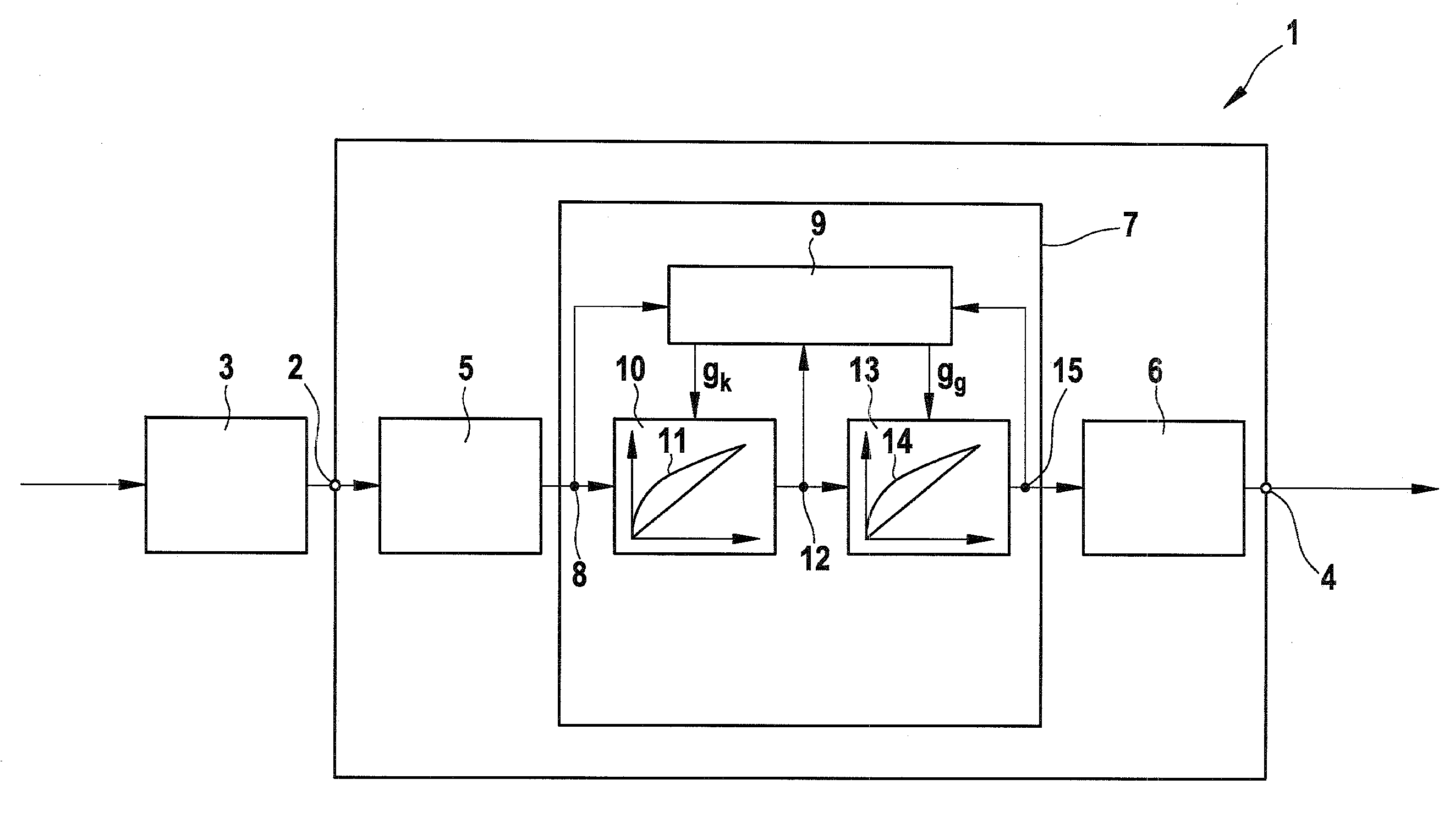
[0034]The image processing system 1 further comprises an optional pre-processing image unit 5 for pre-processing the input images and an optional post-processing unit 6 for post-processing the output images. Sequentially between the pre-processing image unit 5 and post-processing unit 6 a detail enhancing unit 7 as the invention is arranged to receive the pre-processed input images and to release the output images. The output images may be displayed on a monitor or the like.

[0035]At a first measurement node 8 a statistical measurement is carried out on the input image, thereby deriving a statistical measurement result, which is embodied as a median value, a mode value or a skewness value of the input image or of part of the input image. In general any statistical measurement may be used retrieving information about the intensity or luminance distribution of the pixels of the input image. The measurement result is guided to a measurement and control unit 9.

[0036]Afterwards the input ...

second embodiment

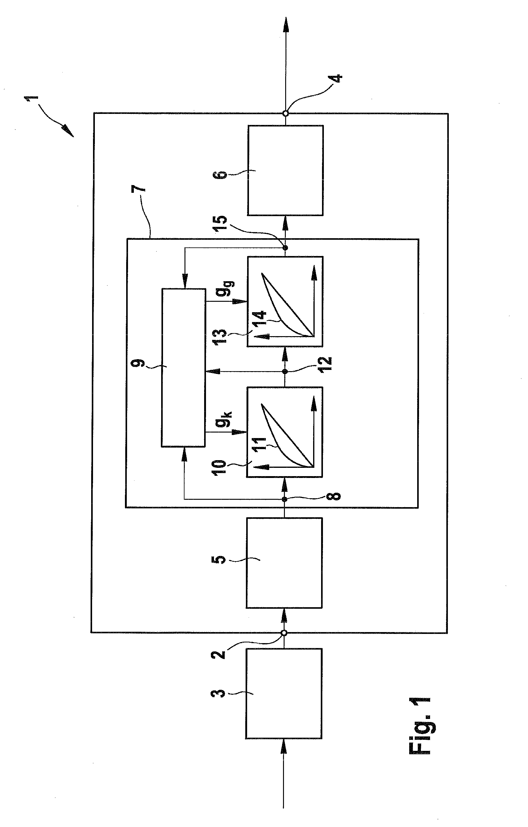
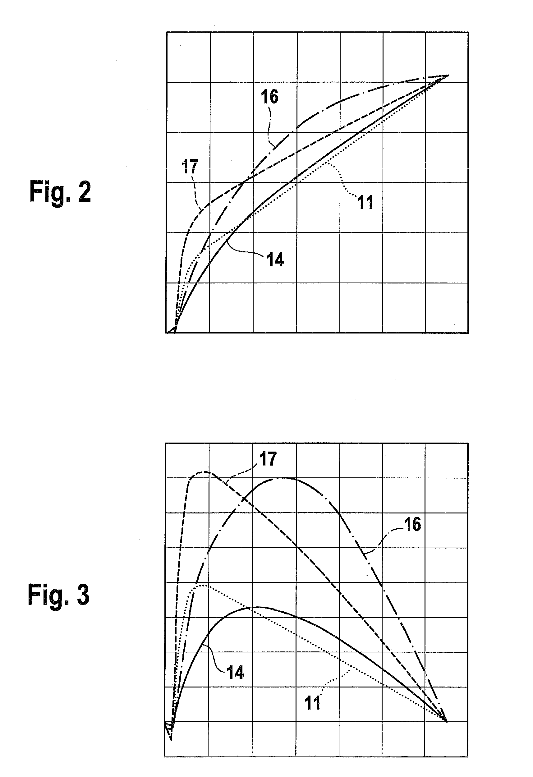
[0044] at the statistical measurement nodes 8, 12 and 15 median measurements Mmt 1, Mmt 2 and Mmt 3 are performed on the input, intermediate and output image, respectively. In an alternative embodiment instead of median other measurements are used, which represent data tendency in the image histogram, for example mode measurement or skewness measurement. Further an auto-exposure measurement is performed in an auto-exposure block 18 on the output image in order to retrieve the average or mean value of the luminance or intensity of the output image. The results of the measurements are guided into the measurement and control unit 9, which determines gain parameters gk and gg for the transfer knee 11 and gamma 14 function.

[0045]A possible control strategy for the image processing unit 7 will be explained with reference to FIG. 7, which shows flow diagram of a control algorithm. The control strategy is to calculate medians at corresponding places and to make them equal to a certain perce...


PUM


Abstract

In the technical field of video cameras gamma correction is an often used technique to compensate the non-linear effects of the CRT (cathode ray tube), in order to enhance visibility in images to be displayed. Gamma correction is—by way of example—expressed by the gamma function: A process for enhancing detail visibility in an input image comprising a step of applying a first transfer function (11) to the input image, thereby generating an intermediate image; a step of performing a statistical measurement (12), Mmt (2) on the intermediate image; a step of applying a second transfer function (14) to the intermediate image, thereby generating an output image; a step of performing a statistical measurement (15), Mmt (3) on the output image, a step of determining gain parameters gg, gk for the first and the second transfer function (11, 14) on basis of the statistical measurement results (8, 12, 15), Mmt (1), Mmt (2), Mmt (3) is proposed.

Description

STATE OF THE ART[0001]The invention relates to a process, an apparatus and a computer program for enhancing detail visibility in an input image.[0002]In the technical field of video cameras gamma correction is an often used technique to compensate the non-linear effects of the CRT (cathode ray tube) in order to enhance detail visibility in images to be displayed. Gamma correction is—by way of example—expressed by the gamma function:Vout=Vinγ,whereby the input and output values are non-negative real values, typically in a predetermined range such as 0 to 1.[0003]The document DE 32 38 281 A1 discloses a digital video-processing system using the above-described or a similar gamma-correction for generating a gamma-corrected video signal, whereby the parameters for the gamma-correction are determined by two resistors.[0004]Using “standard” gamma correction—as described above—often does not satisfy the user completely because it is observed that the dark image details are not sufficiently...

Claims


Application Information

Patent Timeline
IPC IPC(8): G06K9/40
CPCH04N5/202H04N1/4074
Inventor KLIJN, JANJELLEMA, HELIOSCVETKOVIC, SACHA
Owner ROBERT BOSCH GMBH
Why Eureka
Try Eureka