AI technical title is built by Patsnap AI team. It summarizes the technical point description of the patent document.
a technology of white light and white light, applied in semiconductor lasers, lighting and heating apparatuses, instruments, etc., can solve the problem that most of the backscattered light will again leave the converter, and achieve the effect of greater tolerance of material parameters
Active Publication Date: 2017-03-21
SCHOTT AG
View PDF23 Cites 2 Cited by
Summary
Abstract
Description
Claims
Application Information
AI Technical Summary
This helps you quickly interpret patents by identifying the three key elements:
Problems solved by technology
Method used
Benefits of technology
Benefits of technology
[0006]The invention is based on the object to provide an arrangement for adjusting the color location of light, which allows for greater tolerances in material parameters such as thickness of the converter, doping of the converter material, light scattering in the converter, and which allows for use of converter materials in which the white spectral region cannot be achieved by conversion alone.
[0009]However, it is also possible to work with a scattering layer, for example a thin paint coat. Usually, an advantage of such a layer is that the portion of excitation light which is reflected, is not reflected specularly but diffusely, i.e. is backscattered. In this manner, the angular distribution of the reflected excitation light better combines with the converted light. If, however, separation of the two light components is not disadvantageous in the optical system, or is even desirable, specular reflection at a dichroic or metallic layer may be favorable as well. If, when using a scattering layer, specular reflection at the interface to the optically denser medium of the converter is absolutely undesirable, for example because the specular portion would produce undesirable optical effects or because the fraction of converted light is to be increased without reducing the fraction of scattered light, an anti-reflection layer (R<0.05, more preferably R<0.01) for the excitation light and the converted light is applied to the converter first, and thereupon the scattering layer.
Problems solved by technology
However, since the absorption length for the converted light in the converter is long, most of the backscattered light will again leave the converter.
Method used
Image
Click on the blue label to locate the original text in one second.
Reading with bidirectional positioning of images and text.
Examples
Embodiment Construction
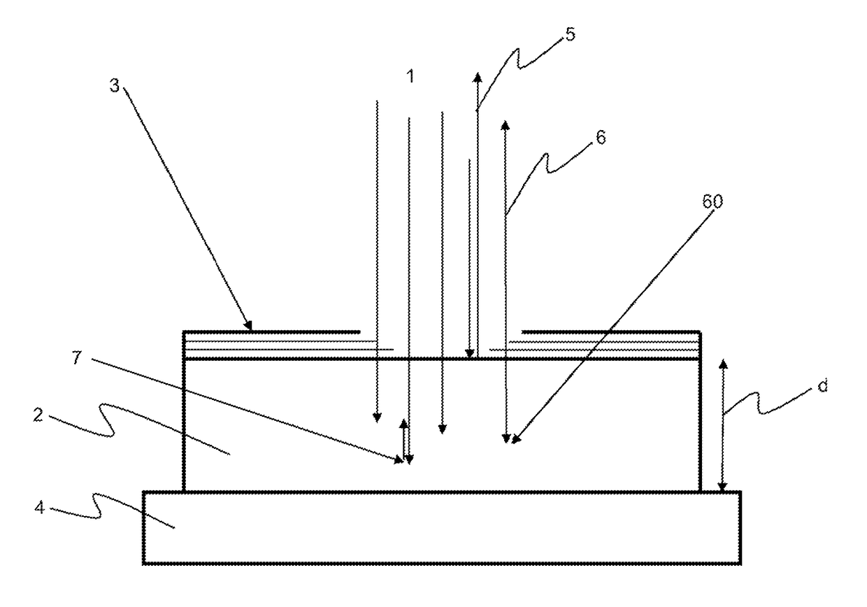
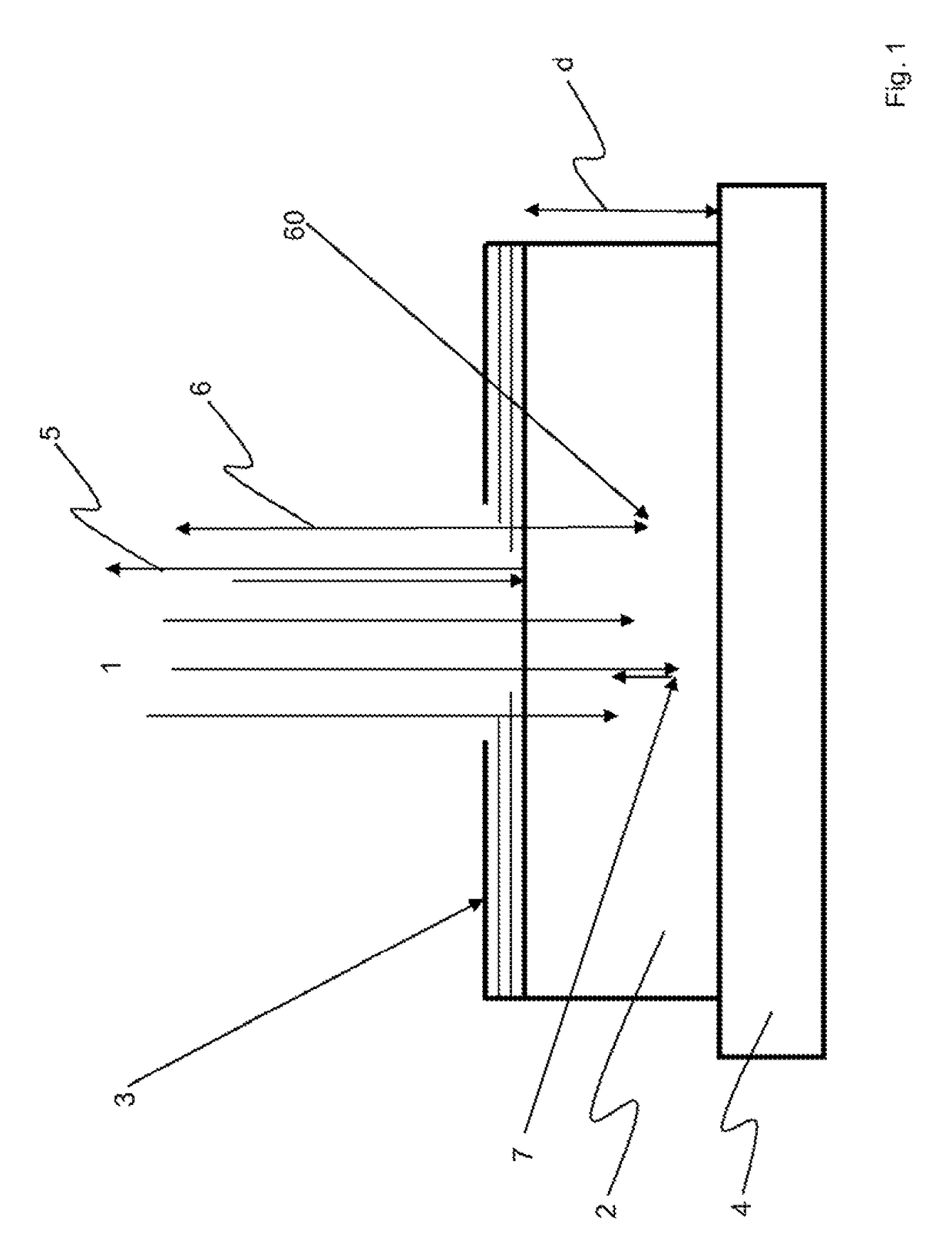
[0018]FIG. 1 schematically illustrates an arrangement for generating white light, which comprises an excitation light source for blue light 1, e.g. a diode laser, and a converter 2 which has a coating 3 on its surface and which is attached on a carrier or support 4. The converter material may be a Ce:YAG ceramic material. Coating 3 is an optical coating for which a dichroic layer or a thin metallic layer is employed. Coating 3 divides the excitation light beam into a portion of reflected light and a portion of entering light. For the purpose of defining these fractions of light, an angle of the incident light to the surface of the converter is usually adjusted to be unequal to 90°. The entering blue light 1 is converted into yellow light 6 by the converter 2, and this the more, the more deeply the light penetrates into the converter, and is output as a light lobe, not shown. A conversion point is indicated at 60. From there, the converted light propagates in all directions. Accordin...
PUM
Property
Measurement
Unit
angle of incidence
aaaaa
aaaaa
angle of incidence
aaaaa
aaaaa
angle
aaaaa
aaaaa
Abstract
An arrangement for generating white light is provided. The arrangement generates the white light by combining blue light and yellow light. The yellow light originates from a converter which transforms into yellow light virtually all blue light that enters the converter.
Description
CROSS REFERENCE TO RELATED APPLICATIONS[0001]This application is a continuation of International Application No. PCT / EP2013 / 054708 filed Mar. 8, 2013, which claims the benefit of U.S. Provisional Application Ser. No. 61 / 614,040, filed Mar. 22, 2012 and claims benefit under 35 U.S.C. §119(a) of German Patent Application No. 10 2012 005 658.3, filed Mar. 22, 2012, the entire contents of all of which are incorporated herein by reference.BACKGROUND[0002]1. Field of the Disclosure[0003]The invention relates to an arrangement for generating in particular white light using blue light and a converter for converting blue light into yellow light and by combining these spectral components.[0004]2. Description of Related Art[0005]Such white light generating arrangements are widely known such as, for example, those disclosed in: WO 2004 / 105647A1, JP 2009105125, U.S. Pat. No. 7,654,712 B2, U.S. 2007 / 189352A1, U.S. Pat. No. 7,758,224 B2, U.S. Pat. No. 7,433,115 B2, U.S. Pat. No. 7,356,054 B2, and ...
Claims
Application Information
Patent Timeline
Application Date:The date an application was filed.
Publication Date:The date a patent or application was officially published.
First Publication Date:The earliest publication date of a patent with the same application number.
Issue Date:Publication date of the patent grant document.
PCT Entry Date:The Entry date of PCT National Phase.
Estimated Expiry Date:The statutory expiry date of a patent right according to the Patent Law, and it is the longest term of protection that the patent right can achieve without the termination of the patent right due to other reasons(Term extension factor has been taken into account ).
Invalid Date:Actual expiry date is based on effective date or publication date of legal transaction data of invalid patent.

