Solenoid Valve having Adjustable Spring Force

a technology of spring force and solenoid valve, which is applied in the direction of valve operating means/release devices, vehicle sub-unit features, braking systems, etc., can solve the problems of bolt insertion, cost-intensive, bolt tilting, etc., and achieve the effect of facilitating the mounting of the sub-assembly

Active Publication Date: 2020-02-06
ROBERT BOSCH GMBH
View PDF0 Cites 0 Cited by
  • Summary
  • Abstract
  • Description
  • Claims
  • Application Information

AI Technical Summary

Benefits of technology

[0025]This means that a sleeve is provided. This sleeve is positioned inside the axial passage of the armature and in particular pressed in place. The sleeve may here help fix the plunger in a premounted armature assembly, since this must retain a pre-pressure from the compression spring. The sleeve may form a stop for the plunger, so that this is not pushed out of the axial passage but can retain the set pre-pressure. Thereby advantageously, a subassembly for the armature may be formed which can be handled separately. This facilitates mounting of the subassembly in that the plunger is fixed in the armature by the inserted sleeve.
[0026]Furthermore, the sleeve may allow guidance for the plunger and guide this on its movement. It is furthermore provided that a gap is formed between the sleeve and the plunger, and runs in the axial direction at least over a part region of the inner face. This allows a fluid balance between a working chamber above the armature and an inner chamber of the axial passage delimited by the closure element on movement of the armature. Advantageously, such a gap allows easy exchange of fluid on movement of the armature. This avoids forces which counter a desired armature movement, for example due to blocked fluid. The gap may be configured as a radial play over the full circumference. Furthermore, the gap may be formed over the entire length of the sleeve.

Problems solved by technology

Insertion of the bolt is however relatively complex and cost-intensive, for example a targeted assembly is necessary; furthermore, when installing the bolt in the axial passage, the bolt can tilt.

Method used


Image

  • Solenoid Valve having Adjustable Spring Force

Examples


Embodiment Construction

[0033]It is pointed out that the features listed individually in the description may be combined with each other in any technically sensible fashion and disclose further embodiments of the invention. Further features and the suitability of the invention arise from the description of exemplary embodiments with reference to the attached figures.

[0034]The drawings show:

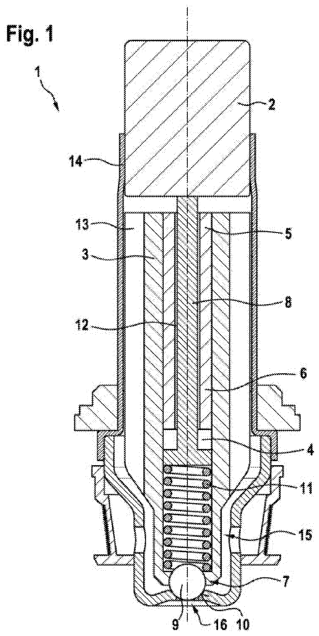
[0035]FIG. 1 an extract of a diagrammatic, sectional view of a solenoid valve according to an embodiment according to the invention.

[0036]FIG. 1 shows in a longitudinal, sectional depiction a solenoid valve 1 for a brake system of a motor vehicle. The solenoid valve 1 comprises a housing 14 which is formed as a cylindrical housing and in which an also cylindrical armature 3 is arranged so as to be longitudinally displaceable, in particular axially movable. A pole core 2, which is connected to or arranged in series with the armature 3, is assigned to an upper end of the armature 3 and fixed in the housing 14 for example b...


PUM


Abstract

A solenoid valve, in particular for controlling a brake pressure of a wheel brake of a motor vehicle, includes a pole core, an axially moveably mounted armature, a valve element, a closure element, a plunger, and a pressure spring. One end of the armature is associated with the pole core. The valve sealing element is arranged at another end of the armature. The armature has an axial through-opening. The closure element is force-lockingly and/or interlockingly retained in the axial through-opening in a selectable position. The plunger is axially moveably mounted in the axial through-opening, which provides a connection to the pole core in an installation position. The pressure spring is positioned in the axial through-opening and is retained in a pretensioned manner between the plunger and the closure element. The closure element is designed as a three-dimensionally convex element.

Description

[0001]The present invention concerns a solenoid valve, in particular for controlling a brake pressure of a wheel brake of a motor vehicle, comprising an axially moveably mounted armature, wherein one end of the armature is assigned to a pole core and a valve sealing element is arranged at another end of the armature, wherein the armature has an axial passage, wherein a closure element is retained in a selectable position in the axial passage by force fit and / or form fit, and a plunger is axially moveably mounted in the axial passage and provides a connection to the pole core in an installation position, wherein a compression spring is positioned in the axial passage, wherein the compression spring is held under preload between the plunger and the closure element, wherein the solenoid valve is characterized in that the closure element is designed as a three-dimensionally convex body.PRIOR ART[0002]Solenoid valves, armatures and methods for production of the generic type are known fro...

Claims


Application Information

Patent Timeline
Patent Type & Authority Applications(United States)
IPC IPC(8): B60T15/02F16K31/06
CPCB60T15/025F16K31/0665B60T8/363B60Y2400/81F16K31/10F16K31/0693F16K31/0686F16K31/0696F16K1/14B60T15/028
Inventor DINERMAN, MICHAELREICHERT, MICHAELHAEUSSER, BERND
Owner ROBERT BOSCH GMBH
Why Eureka
Try Eureka