

Polyurea perimeter seal for an aircraft antenna or other aircraft part
a technology of polyurea and perimeter seals, applied in the direction of coatings, mechanical equipment, transportation and packaging, etc., to achieve the effect of improving uv resistan
- Summary
- Abstract
- Description
- Claims
- Application Information
AI Technical Summary
Benefits of technology
Problems solved by technology
Method used
Image

Examples
Embodiment Construction
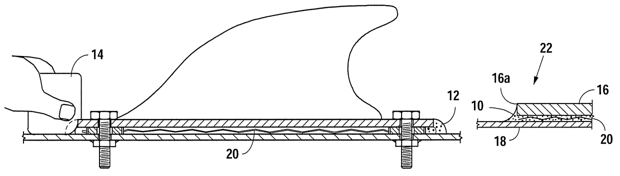
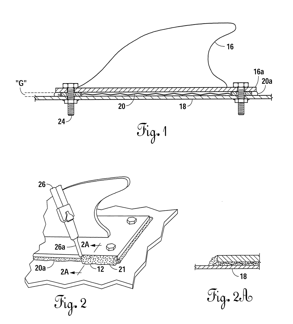
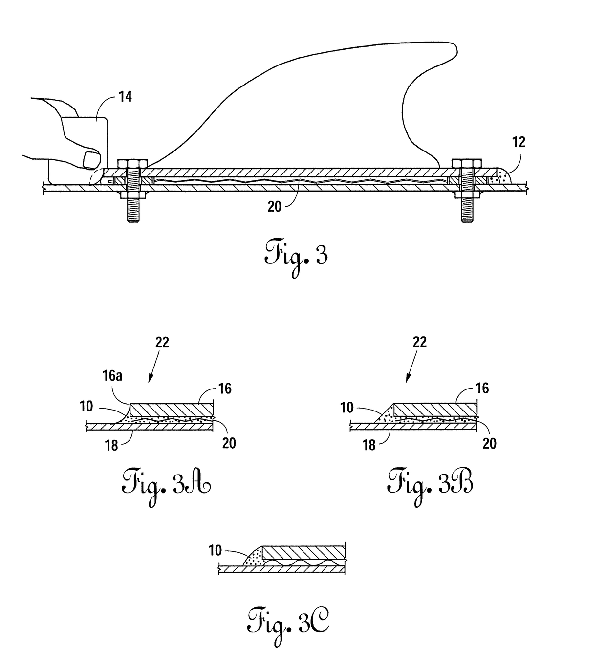
[0051]FIGS. 1-4A illustrate an assembly comprising an aircraft base, such as a fuselage 18, and an aircraft workpiece, such as an aircraft antenna 16, having an outer perimeter 16a and optionally an elastomeric gasket. In one case, the gasket is a polyurethane gasket 20 having a gasket body of cured polyurethane (such as disclosed in the patents incorporated herein by reference, for example) with an outer perimeter 20a. The gasket may be under compression between the base and the workpiece, such as compression generated by a multiplicity of fasteners 24. The figures also illustrate a method of making the assembly and the method of use of the assembly. A kit for use when applying the perimeter seal is also illustrated.
[0052]Sometimes the gasket, having a gel, gel-like or pliable body, when compressed, may spread laterally outward at its perimeter 20a as the workpiece is being torqued down towards the base. Upon compression, perimeter 20a of the gasket body may reach or not reach (und...
PUM
| Property | Measurement | Unit |
|---|---|---|
| temperatures | aaaaa | aaaaa |
| temperatures | aaaaa | aaaaa |
| temperature | aaaaa | aaaaa |
Abstract
Description
Claims
Application Information