Motor with thrust bearing

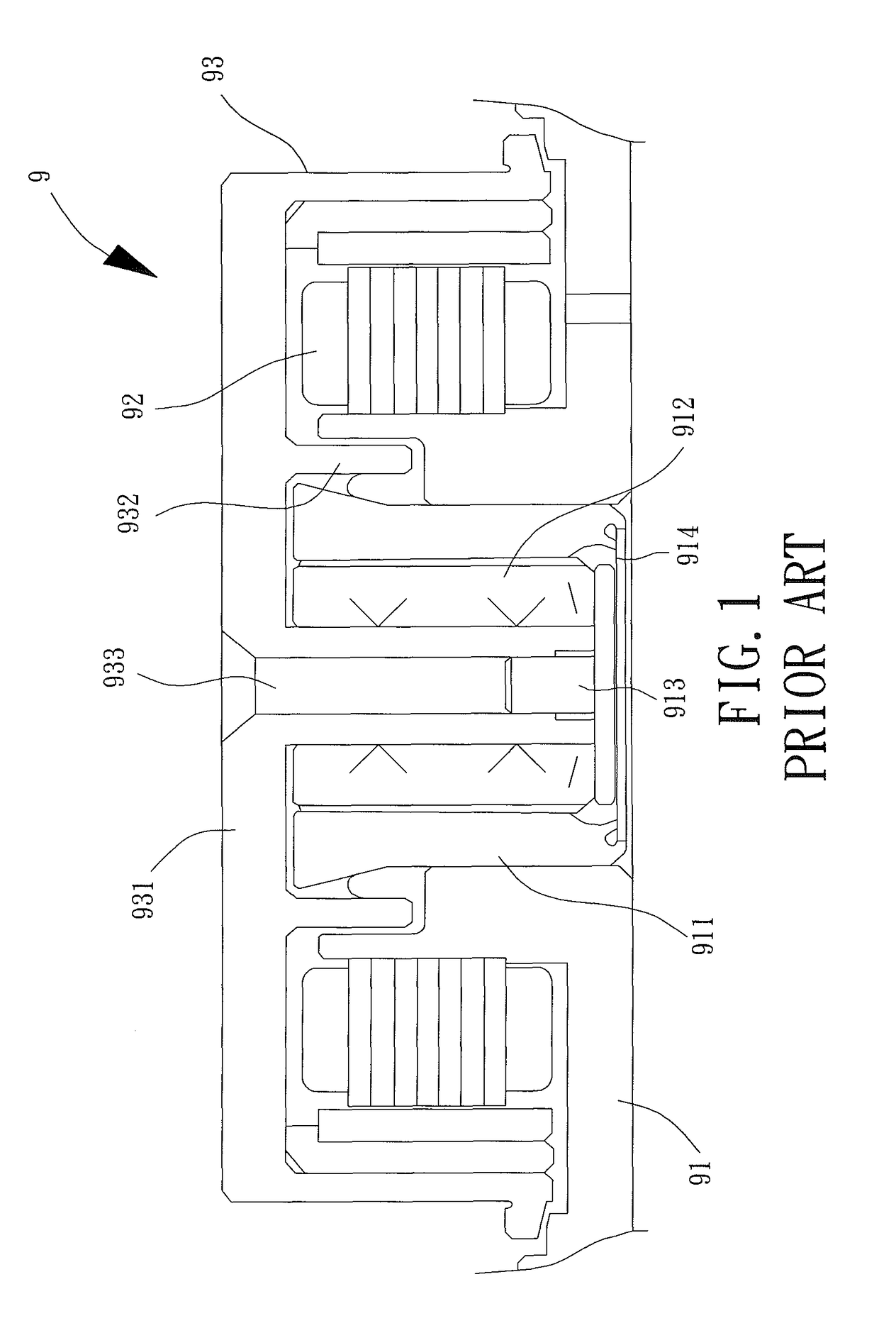
a technology of thrust bearings and motors, which is applied in the direction of record information storage, magnetic circuit shape/form/construction, instruments, etc., can solve the problems of difficult to smoothly perform the connection of the motor b>9/b>, the above steps of the motor assembly are complex, and the motor b>9/b> is difficult to achieve smooth connection, etc., to achieve low manufacturing cost, simple assembly process, and low cost

Active Publication Date: 2017-09-19
SUNONWEALTH ELECTRIC MACHINE IND
View PDF21 Cites 2 Cited by
  • Summary
  • Abstract
  • Description
  • Claims
  • Application Information

AI Technical Summary

Benefits of technology

[0008]What is needed is a motor with a thrust bearing, which has a simple structure for easy and fast assembly, low manufacture cost and an ideal performance in oil-preservation.
[0018]Based on the above structures, the assembly of the motor can be achieved by simply disposing the rotating member and the thrust bearing into the bearing sleeve via the opening end and coupling the hub with the shaft of the rotating member. Therefore, the assembly process is simple. In addition, the bearing sleeve has one end being a sealing end. Overall, the motor has advantages such as convenient assembly, low manufacturing cost and high oil-preserving effect.

Problems solved by technology

It is apparent that the above steps for assembly of the motor 9 are complex.
Besides, since the connection between the shaft 933 and the pushing board 913 is inside the thrust bearing 912, it is also difficult to perform this connection smoothly.
Therefore, the conventional motor 9 has problems such as bad oil-preservation, high operation noise caused by oil-leakage, high cost of manufacture, and short lifetime.

Method used


Image

  • Motor with thrust bearing
  • Motor with thrust bearing
  • Motor with thrust bearing

Examples


Embodiment Construction

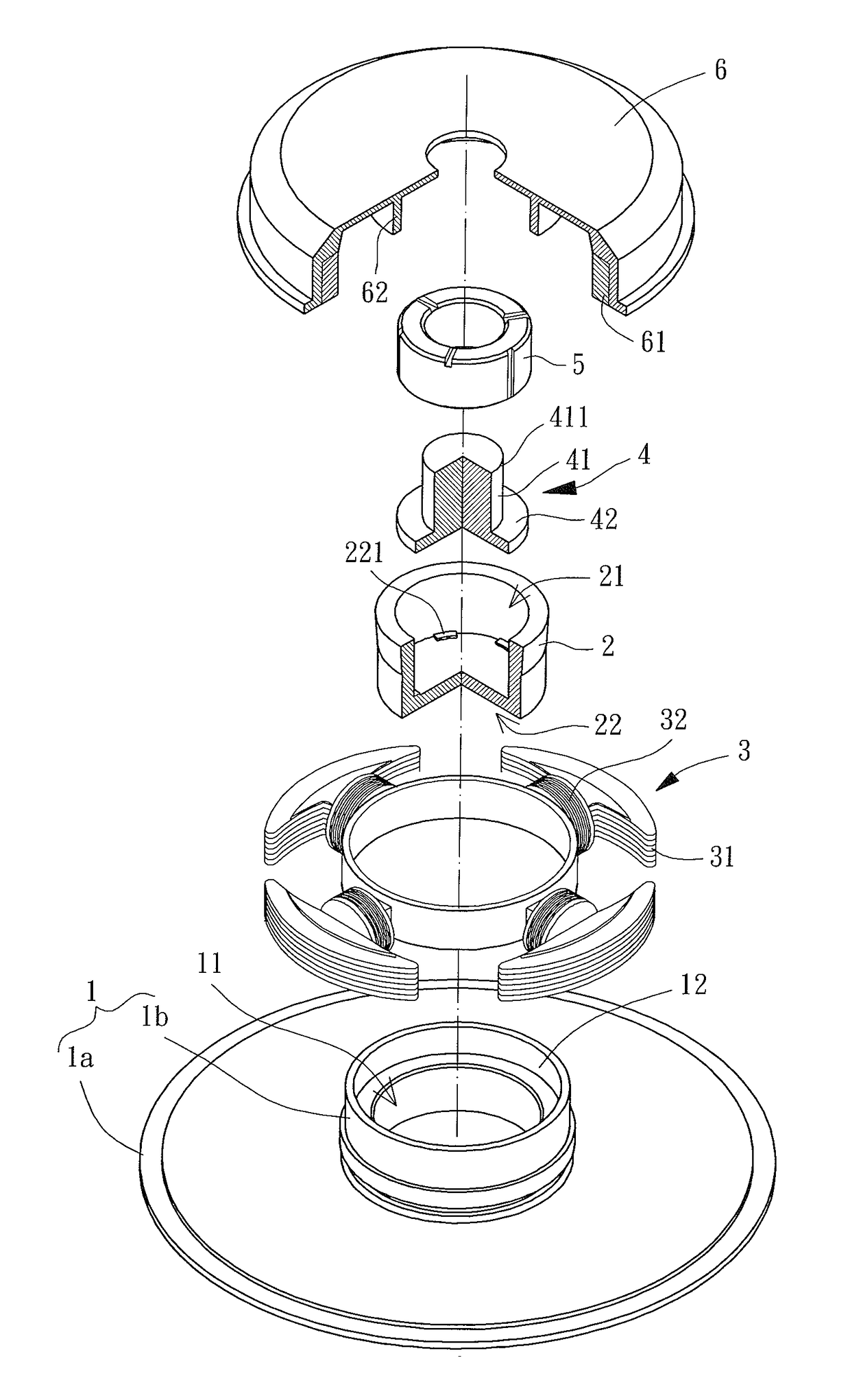
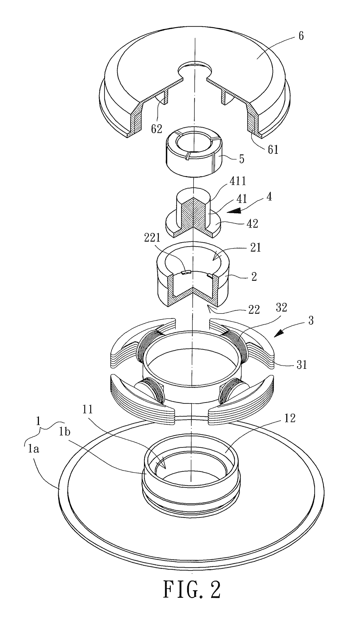
[0029]Referring to FIG. 2, a preferred embodiment of a motor with a thrust bearing of the present invention is shown and includes a base 1, a bearing sleeve 2, a stator 3, a rotating member 4, a thrust bearing 5, and a hub 6. The bearing sleeve 2 and the stator 3 connect with the base 1, the bearing sleeve 2 receives the rotating member 4 and the thrust bearing 5, and the hub 6 couples with the rotating member 4.

[0030]Specifically, the base 1 has a connecting portion 11 that can be of any structure for connecting with the bearing sleeve 2. Furthermore, the base 1 may include a plate 1a and a tube 1b, and the tube 1b connects to a center part of the plate 1a. The tube 1b has an axial hole extending therethrough axially. The connecting portion 11 is in the form of a through-hole inside which the bearing sleeve 2 can be engaged.

[0031]The bearing sleeve 2 couples with the connecting portion 11 of the base 1 and can be of any structure capable of receiving the rotating member 4 and the t...


PUM

PropertyMeasurementUnit
outer diameteraaaaaaaaaa
dust-resistanceaaaaaaaaaa
structureaaaaaaaaaa

Abstract

A motor includes a base, a bearing sleeve, a stator, a rotating member, a thrust bearing, and a hub. The bearing sleeve is arranged with the base and has an opening end and a sealing end opposite to each other. The stator connects with the base or the bearing sleeve. The rotating member is arranged inside the bearing sleeve and includes a shaft and a limiting portion adjacent to the sealing end. A first end of the shaft connects with the limiting portion, and a second end of the shaft has a coupling portion adjacent to the opening end. The thrust bearing is arranged between the shaft and an inner surface of the bearing sleeve, so that the limiting portion is between the thrust bearing and the sealing end. The hub connects with the coupling portion of the shaft and has a permanent magnet corresponding to the stator.

Description

BACKGROUND OF THE INVENTION[0001]1. Field of the Invention[0002]The present invention generally relates to a motor with thrust bearing and, more particularly, to a motor of simple structure and easy to be assembled.[0003]2. Description of the Related Art[0004]Referring to FIG. 1, a sketch diagram of a conventional motor with a thrust bearing is shown, which is identified with a reference number of “9” and which has a seat 91, a stator 92 and a rotor 93. The seat 91 couples with a bearing housing 911 receiving a thrust bearing 912 and a pushing board 913 inside. The bearing housing 911 has two opposite openings for the rotor 93 to extend into the thrust bearing 912 and to couple with a lid 914 respectively. The stator 92 couples with an outer periphery of the seat 91. The rotor 93 includes a hub 931 integrally forming an annular wall 932 and a shaft 933. The annular wall 932 is positioned between the seat 91 and the bearing housing 911, to provide functions such as dust-resistance an...

Claims


Application Information

Patent Timeline
Patent Type & Authority Patents(United States)
IPC IPC(8): H02K5/16H02K1/18F16C43/02H02K7/08H02K5/10G11B19/20F16C17/10
CPCH02K1/187F16C43/02G11B19/2009H02K5/10H02K7/085F16C17/107F16C2370/12H02K2205/03
Inventor HORNG, ALEXWANG, KO-CHIEN
Owner SUNONWEALTH ELECTRIC MACHINE IND
Why Eureka
Try Eureka