Method for controlling bulk density of carbon nanotube agglomerate

a carbon nanotube and aggregate technology, applied in the direction of catalyst activation/preparation, metal/metal-oxide/metal-hydroxide catalyst, physical/chemical process catalyst, etc., can solve the problem of limited industrial application and use of carbon nanotubes, high arc production costs or expensive laser equipment, and the limitation of direct control of the diameter and length of carbon nanotubes to industrially applicable dimensions. , to achieve the effect of improving physical properties and being easy to disperse in

Active Publication Date: 2017-11-07
LG CHEM LTD
View PDF23 Cites 2 Cited by
  • Summary
  • Abstract
  • Description
  • Claims
  • Application Information

AI Technical Summary

Benefits of technology

[0013]It is an object of the present invention to provide a method for producing a carbon nanotube aggregate with controlled bulk density in high yield in which the carbon nanotubes have a bundle type structure that facilitates dispersion in and mixing with a polymer during compounding with the polymer.
[0018]The method of the present invention enables the production of a bundle type carbon nanotube aggregate that is readily dispersible in and miscible with other materials and whose bulk density is controllable. Therefore, the bundle type carbon nanotube aggregate can be used to manufacture a composite material with improved physical properties. As a result, the carbon nanotube aggregate is suitable for use in various fields, such as energy materials, functional composites, pharmaceuticals, batteries, semiconductors, display devices, and manufacturing methods thereof.

Problems solved by technology

However, carbon nanotubes have a limitation in directly controlling the diameter and length to industrially applicable dimensions for practical use owing to their primary structure.
Accordingly, the industrial application and use of carbon nanotubes are limited despite their excellent physical properties.
However, arc discharge and laser ablation are not appropriate for mass production of carbon nanotubes and require high arc production costs or expensive laser equipment.
Chemical vapor deposition using a vapor dispersion catalyst has the problems of a very low synthesis rate and too small a size of final carbon nanotube particles.
Chemical vapor deposition using a substrate-supported catalyst suffers from very low efficiency in the utilization of a reactor space, thus being inappropriate for mass production of carbon nanotubes.

Method used


Image

  • Method for controlling bulk density of carbon nanotube agglomerate
  • Method for controlling bulk density of carbon nanotube agglomerate
  • Method for controlling bulk density of carbon nanotube agglomerate

Examples


example 1

[0103]A. Preparation of Aqueous Solution of Graphitization Metal Catalyst Precursor

[0104]2,424 g of Fe(NO3)2.6H2O, a precursor of Fe as a graphitization catalyst, was added to 2,000 g of water in flask A. The aqueous metal solution was observed to be clear and free of precipitates.

[0105]B. Preparation of Support

[0106]Aluminum trihydroxide (Al(OH)3, ATH) as an aluminum-based support was primarily calcined at 300-500° C. for 4 h to obtain a support. 2,000 g of the support was placed in flask B. XRD analysis revealed the presence of 40 wt % or more of AlO(OH) in the calcined support.

[0107]C. Preparation of Supported Catalyst

[0108]4,424 g of the solution in flask A was added to flask B such that the number of moles of Fe was 30 moles when the number of moles of the support (2,000 g) was assumed to be 100 moles. The mixture was weighed and aged with stirring in a thermostatic bath at 60° C. for 5 min to sufficiently support the graphitization catalytic metal precursor on ATH400. The aged...

example 2

[0115]Changes in the bulk density of carbon nanotube aggregates were observed with varying temperatures for catalyst calcination. Catalysts were prepared in the same manner as in Example 1, except that Co / V (10:1 molar ratio) was used instead of Fe, the primary calcination temperature was fixed to 400° C., the secondary calcination was performed at different temperatures of 600-700° C., and citric acid was added in a molar ratio of 1:23 relative to Co. Carbon nanotube aggregates were synthesized using the catalysts in the same manner as in Example 1. When the reaction times were 1 h and 2 h, the yields and bulk densities of the carbon nanotube aggregates are shown in Table 2.

[0116]

TABLE 2Temperaturefor catalystReactionBulkcalcinationtimeYielddensityEntryCatalyst(° C.)(h)(times)(kg / m3)1CoV / ATH400-600600118.5132236.31442CoV / ATH400-650650126.3242255.53563CoV / ATH400-675675125.5044257.00604CoV / ATH400-700700124.0337251.0052

[0117]The results in Table 2 are graphically shown in FIG. 6. The ...

example 3

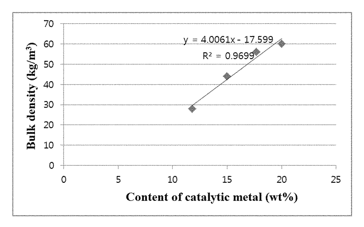
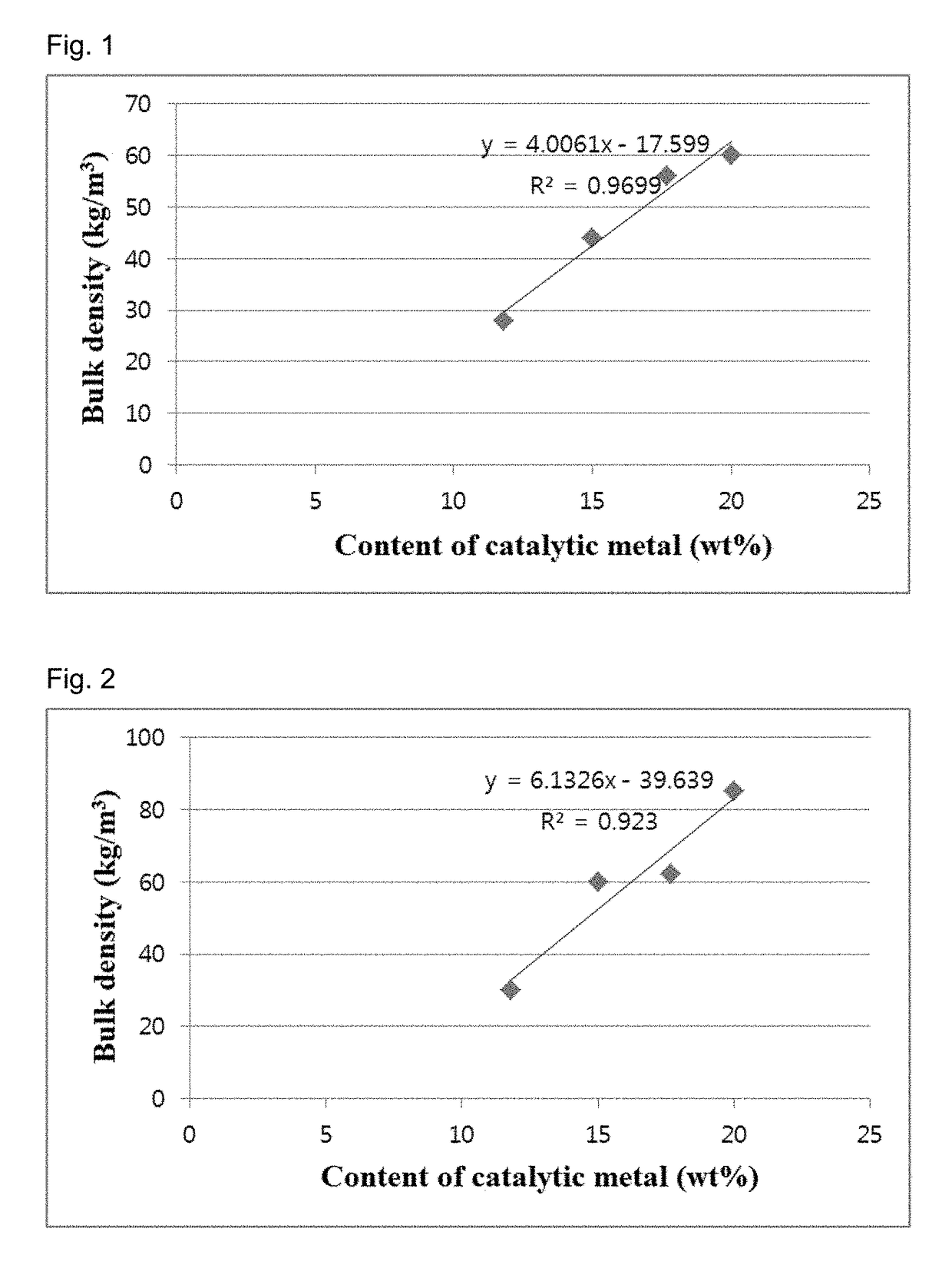
[0118]Catalysts were prepared in the same manner as in Example 2, except that the secondary calcination temperature was fixed to 675° C. and the Co content was changed as shown in Table 3. Carbon nanotube aggregates were synthesized using the catalysts in the same manner as in Example 2. When the reaction times were 1 h and 2 h, the yields and bulk densities of the carbon nanotube aggregates are shown in Table 3.

[0119]

TABLE 3CoReactionBulkcontenttimeYielddensityEntryCatalyst(wt %)(h)(times)(kg / m3)1CoV / ATH400-67511.8114.7728223.90302CoV / ATH400-67515125.5044257.00603CoV / ATH400-67517.7121.6756240.04624CoV / ATH400-67520121.3660241.9485

[0120]The results in Table 3 are graphically shown in FIG. 7. FIG. 8 shows SEM images of the carbon nanotube aggregates.


PUM

PropertyMeasurementUnit
temperatureaaaaaaaaaa
densityaaaaaaaaaa

Abstract

The present invention relates to a method for producing a carbon nanotube aggregate whose bulk density is easily controllable. Therefore, the present invention provides a carbon nanotube aggregate suitable for use in various fields.

Description

[0001]This application is a National Stage Application of International Application No. PCT / KR2014 / 009231, filed Sep. 30, 2014, and claims priority to and benefit of Korean Patent Application Nos. 10-2014-0129411 filed Sep. 26, 2014, 10-2014-0129449 filed Sep. 26, 2014, 10-2014-0072553 filed Jun. 16, 2014, and 10-2013-0116963 filed Sep. 30, 2013, all of which are hereby incorporated by reference in their entirety for all purposes as if fully set forth herein.BACKGROUND OF THE INVENTION[0002]1. Field of the Invention[0003]The present invention relates to a method for producing a carbon nanotube aggregate, and more particularly to a method for producing a bundle type carbon nanotube aggregate with controlled bulk density.[0004]2. Description of the Related Art[0005]Carbon nanostructures (CNSs) refer collectively to nano-sized carbon structures having various shapes, such as nanotubes, nanohairs, fullerenes, nanocones, nanohorns, and nanorods. Carbon nanostructures can be widely utiliz...

Claims


Application Information

Patent Timeline
Patent Type & Authority Patents(United States)
IPC IPC(8): B01J21/18C01B32/162B01J35/00C01B32/158B01J23/70B01J23/745B01J37/08B01J23/847B01J23/22B01J23/28B01J23/88B01J23/887
CPCB01J21/185B01J23/70B01J23/745B01J23/8472B01J35/0026B01J37/08C01B32/158C01B32/162B01J23/22B01J23/28B01J23/88B01J23/8877C01B2202/22C01B32/16C01B2202/00
Inventor KIM, SUNGJINSON, SEUNGYONGCHO, DONG HYUNKANG, KYUNGYEONCHA, JINMYUNGWOO, JIHEE
Owner LG CHEM LTD
Why Eureka
Try Eureka