
A permanent magnet synchronous motor current filtering and dead zone compensation device and compensation method
A technology of permanent magnet synchronous motor and dead zone compensation, which is applied to the control of electromechanical transmission, control of generator, motor generator control, etc.
Patent Information
- Authority / Receiving Office
- CN · China
- Patent Type
- Patents(China)
- Current Assignee / Owner
- Publication Date
- 2017-01-18
Smart Images
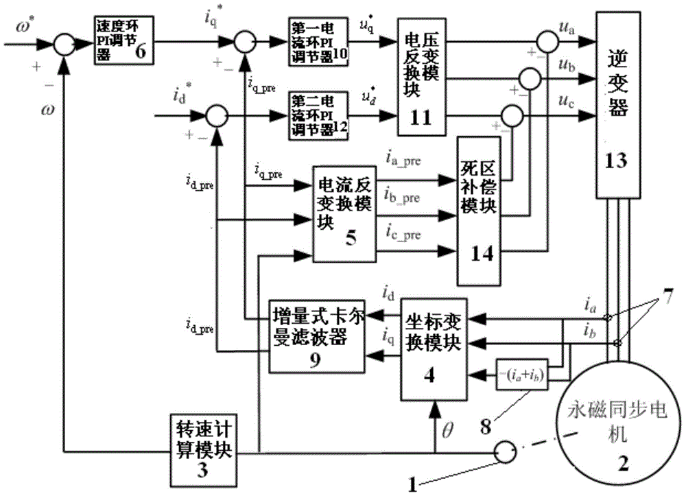
Figure 1 
Figure 2 
Figure 3
Abstract
Description
technical field
[0001] The invention relates to a motor current filtering and dead zone compensation device and compensation method, in particular to a permanent magnet synchronous motor current filtering and dead zone compensation device and compensation method. Background technique
[0002] Permanent magnet synchronous motors have the advantages of high efficiency, high power density, and no carbon brushes, and have been widely used in servo applications. The actual system generally contains a certain degree of noise. The current noise sources of the permanent magnet synchronous motor servo system can be divided into two types. One is the white noise caused by non-ideal factors such as interference and sampling error, which is unavoidable. The other is that because the system is in a state of closed-loop control, the original white noise is adjusted as an input error, causing frequent disturbances in the system output, thereby causing greater noise. For this type of noise...
Examples
Embodiment Construction
[0058] The present invention will be described in detail below in conjunction with the accompanying drawings and embodiments.
[0059] Such as figure 1 As shown, taking the permanent magnet synchronous motor servo system as an example, the present invention includes a position sensor 1, a permanent magnet synchronous motor (PMSM) 2, a speed calculation module 3, a coordinate transformation module 4, a current inverse transformation module 5, and a speed loop PI regulator 6. Current sensor 7, summation module 8, incremental Kalman filter 9, first current loop PI regulator 10, voltage inverse conversion module 11, second current loop PI regulator 12, inverter 13 and die Zone Compensation Module 14 . Wherein the coordinate transformation module 4, the incremental Kalman filter 9 and the first current loop PI regulator 10 constitute the q-axis current loop; the coordinate transformation module 4, the incremental Kalman filter 9 and the second current loop PI regulator 12 forms t...