Optical fiber display

A technology of display and optical fiber, applied in the field of optical fiber display

Inactive Publication Date: 2008-04-23
HONG FU JIN PRECISION IND (SHENZHEN) CO LTD +1
View PDF5 Cites 0 Cited by
  • Summary
  • Abstract
  • Description
  • Claims
  • Application Information

AI Technical Summary

Problems solved by technology

[0004] In order to solve the problem that the optical fiber display in the prior art requires a projector to generate projection signals, the present invention provides a fiber optic display that directly modulates the light intensity on the optical fiber

Method used


Image

  • Optical fiber display
  • Optical fiber display
  • Optical fiber display

Examples


Embodiment Construction

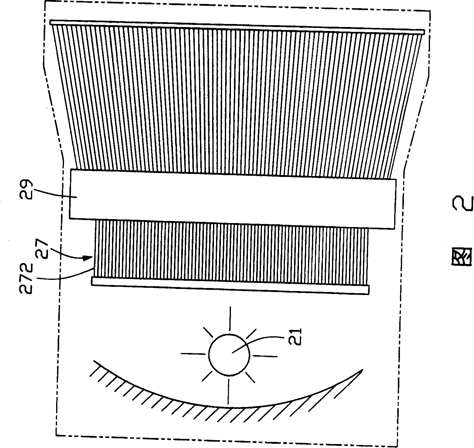
[0018] Please refer to FIG. 2 , which is a schematic structural view of the first embodiment of the fiber optic display of the present invention. The optical fiber display includes a light source 21, an optical fiber bundle 27 and a brightness modulation system 29, wherein the optical fiber bundle 27 includes a plurality of optical fibers 272, wherein one end of the plurality of optical fibers 272 forms a light incident end for receiving the The light emitted by the light source 21 forms a display end at the other end. The light brightness modulation system 29 is arranged between the light incident end and the display end, and is used to control the bending degree of the optical fiber 272 in the optical fiber bundle 27 to realize brightness modulation.

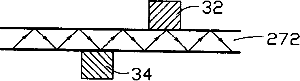
[0019] see Figure 3 to Figure 4 , the brightness modulation system 29 includes a plurality of optical switches corresponding to the optical fibers 272 in the optical fiber bundle, the optical switch includes two retractable ...


PUM


Abstract

The optical fiber display includes one light source, one fiber bundle and one light brightness regulating system. The fiber bundle includes several pieces of fibers, and each of the fibers has one light incoming end to receive the light the light source emits and one other display end. The light brightness regulating system is set between the incoming ends and the display ends to change the bending degree of the fibers and thus to regulate the outgoing light strengths of the fibers. The optical fiber display may further include color filter, light coupling module, band-pass visible light filter and diffusion plate to realize color display or raise display effect.

Description

【Technical field】 [0001] The invention relates to a display, in particular to an optical fiber display. 【Background technique】 [0002] With the continuous development of science and technology in recent decades, various new display technologies have emerged as the times require. At present, flat panel displays of new display technologies mainly include Liquid Crystal Display (LCD), Plasma Display Panel (PDP), projection display, and Organic Light Emitting display (Organic Light Emitting display, OLED). [0003] For a fiber optic display in the prior art, reference may be made to Chinese Patent No. 97243700 published on June 23, 1999. The fiber optic display uses optical fibers in pixels to realize a larger display. like figure 1 As shown, the optical fiber display includes a projector 1, a reflector 2, an optical fiber bundle head 3 and a picture plate 4, wherein the optical fiber bundle head 3 is glued on the same plane by the bundled optical fiber 302 in the most closel...

Claims


Application Information

Patent Timeline
Patent Type & Authority Patents(China)
IPC IPC(8): G02B6/06
Inventor 李俊佑蔡明江江宗韦
Owner HONG FU JIN PRECISION IND (SHENZHEN) CO LTD
Why Eureka
Try Eureka