
Energy-storage type solar energy LED lamp
A technology of LED lamps and solar energy, applied in energy-saving lighting, lamp circuit layout, energy-saving control technology, etc., can solve the problems of increased use cost, influence of use range, large brightness attenuation of LED lamp beads, etc. Extended life and outstanding energy saving effect
- Summary
- Abstract
- Description
- Claims
- Application Information
AI Technical Summary
Problems solved by technology
Method used
Image


Examples
Embodiment Construction
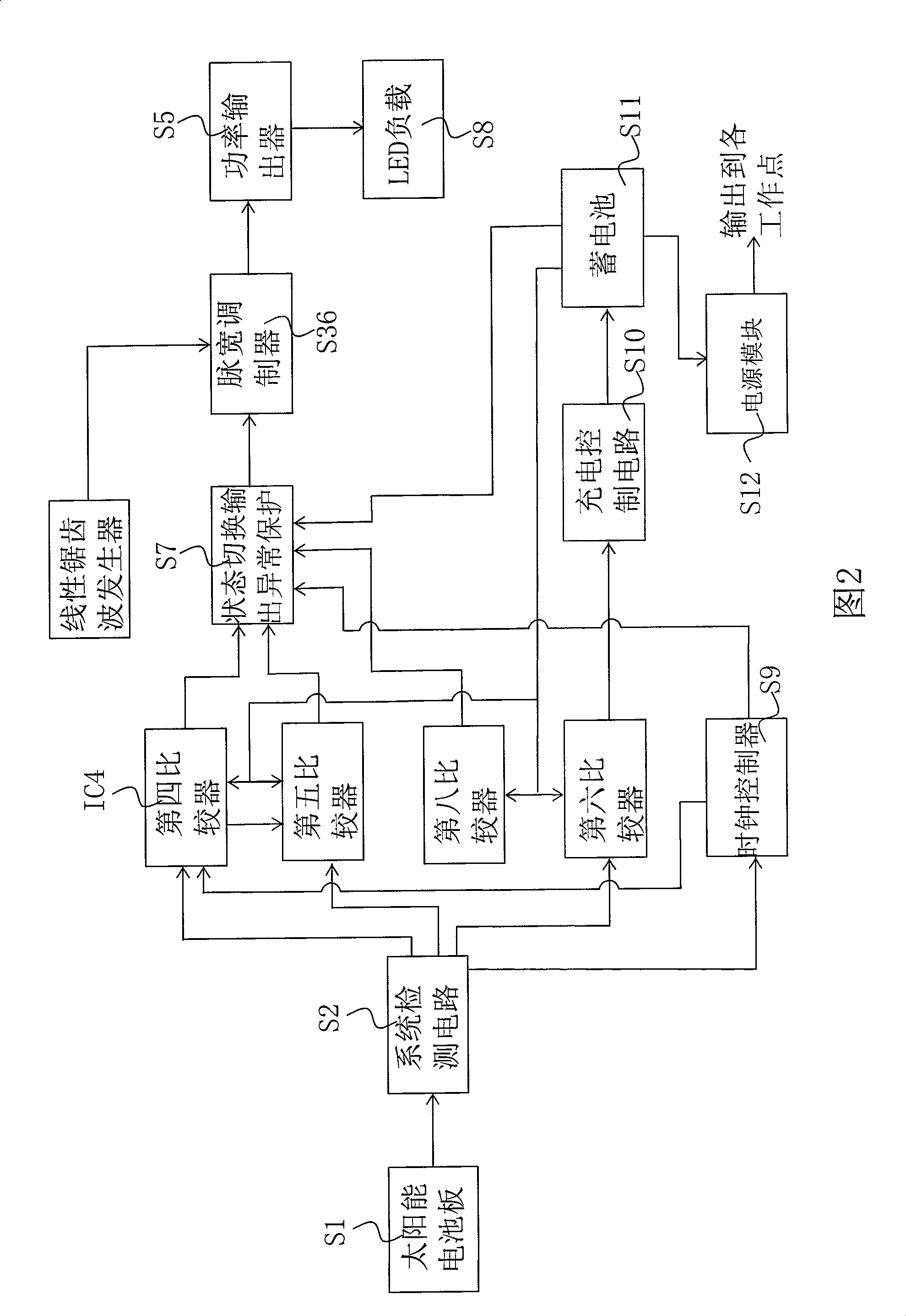
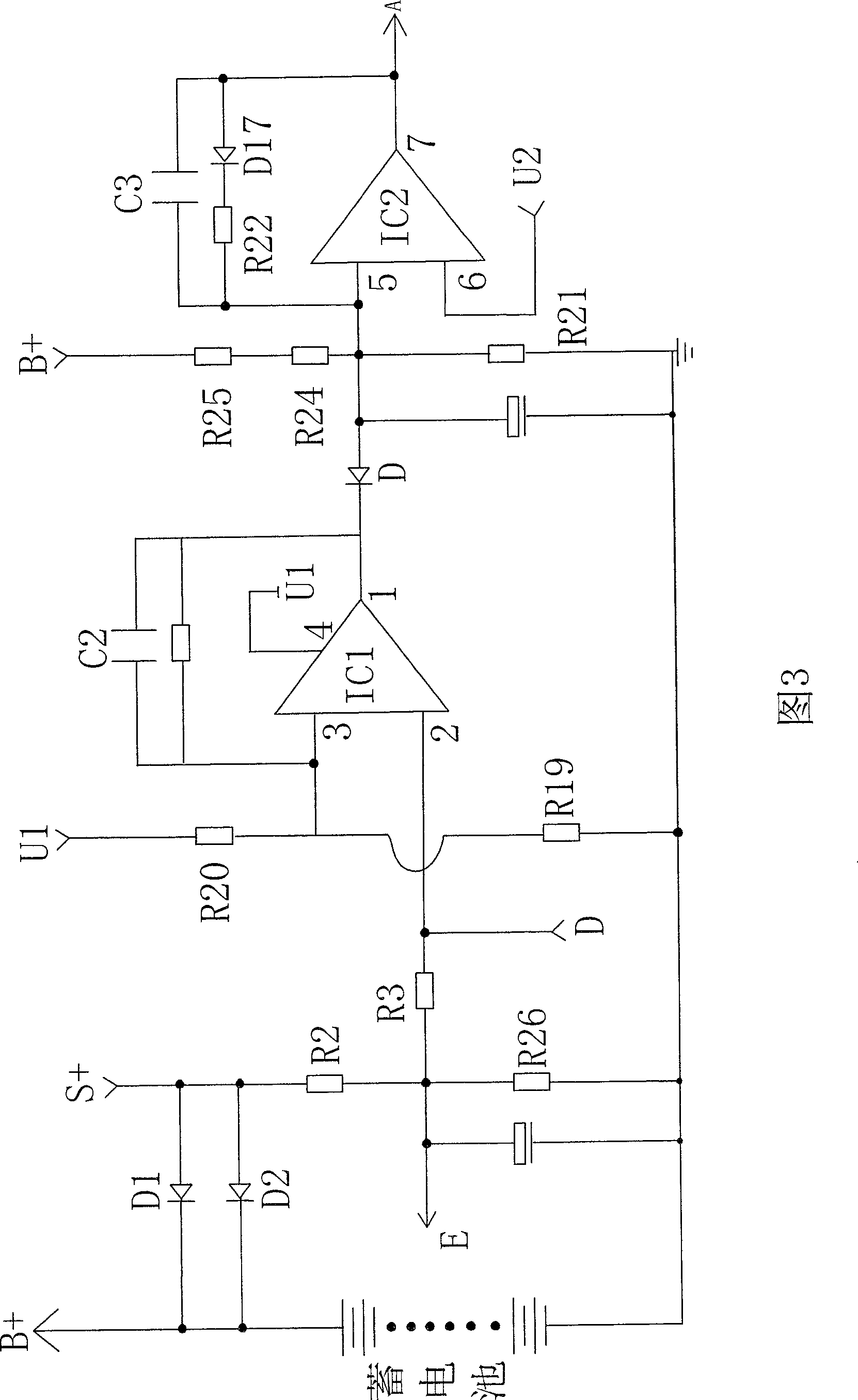
[0019] Refer to Figure 1 to Figure 10 , an energy storage type solar LED lamp, including a solar circuit board S1, a storage battery S11, an LED load S8 and a controller, the controller includes a system detection circuit S2, the input terminal of the system detection circuit S2 is connected to the solar panel S1, and the output The terminal is connected with the state detection circuit S3, the battery voltage detection circuit S6, the clock controller S9 and the charging control circuit S10; the state detection circuit S3, the battery voltage detection circuit S6 and the clock controller S9 are connected to the state switching output abnormality protection circuit S7, and the state switching The output abnormal protection circuit S7 is connected to the power output device S5 through the pulse modulation circuit S4, and the power output device S5 is connected to the LED load S8; the positive pole S+ of the solar panel S1 is connected to the positive pole B+ of the battery S11,...
PUM
 Abstract
Description
Claims
Application Information