Ladle bottom construction method

A ladle bottom and masonry technology, which is applied in construction, building structure, construction material processing and other directions, can solve the problems of excessively flat bottom, increased consumption of refractory materials, and rising costs, so as to reduce production costs and improve usage. The effect of reducing life and cost per ton of steel

Inactive Publication Date: 2009-11-04
武钢集团有限公司
View PDF5 Cites 0 Cited by
  • Summary
  • Abstract
  • Description
  • Claims
  • Application Information

AI Technical Summary

Problems solved by technology

[0003] The disadvantage of this ladle bottom masonry method is that it is equivalent to only two layers of the bottom of the ladle, the bottom of the ladle is too flat, and the thickened castable cannot tighten the working layer, which affects the use effect of the thickened material, resulting in the bottom of the working layer The bricks of the working layer near the nozzle are easy to fall off, and the bricks in the impact zone are easy to form pits after being washed by molten steel. The bricks of the bottom working layer cannot meet the requirements of use, and the safety of use cannot be guaranteed, which affects the service life
At the same time, the strength of the castable is not high, and the resistance to molten steel erosion is not strong, which also affects the life of the bottom brick, which increases the consumption of refractory materials and increases the cost

Method used


Image

  • Ladle bottom construction method

Examples


Embodiment Construction

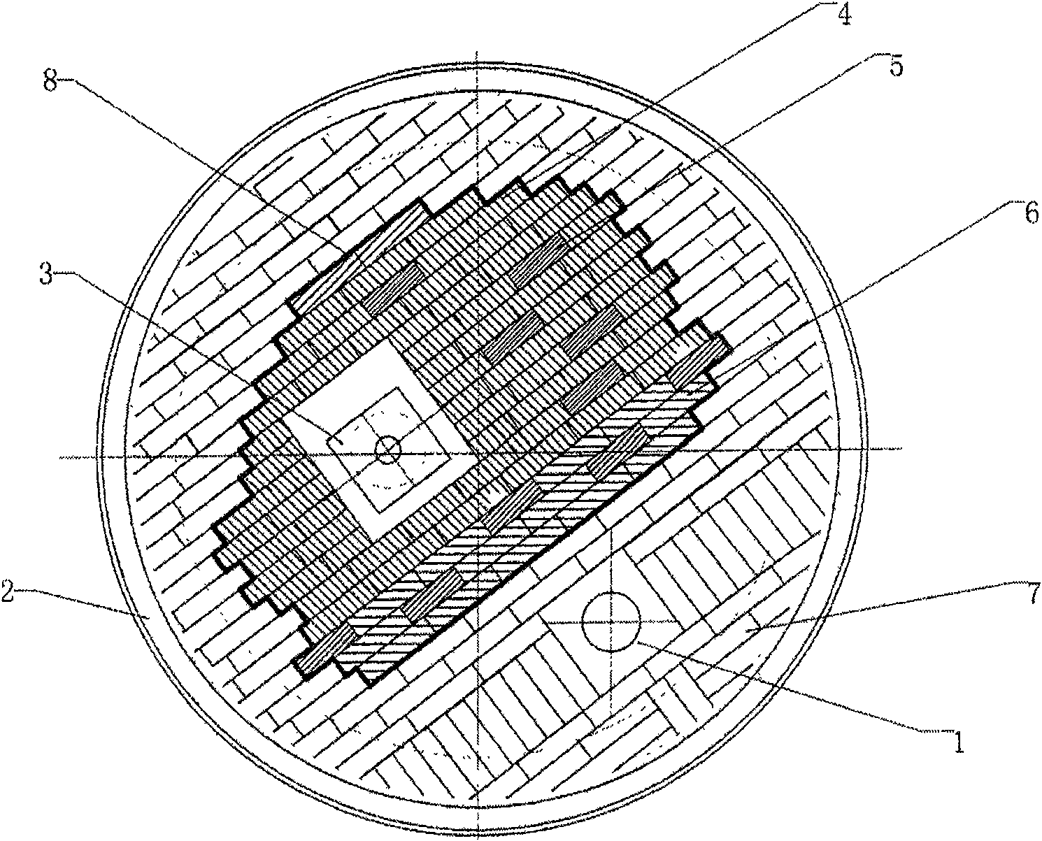
[0013] The masonry method example at the bottom of the ladle of the present invention is:

[0014] 1) The bottom of the masonry ladle starts from nozzle 1, and bricks 7 with a height of 180 mm, a length of 300 mm, and a thickness of 80 mm are used to build the area of ​​the nozzle and the ladle wall 2.

[0015] 2) Two rows of bricks 7, three rows of bricks 6 with a height of 240 mm, a length of 300 mm, and a thickness of 80 mm, and two rows of bricks 4 with a height of 300 mm, a length of 300 mm, and a thickness of 80 mm are successively built between the nozzle 1 and the ventilation brick 3. On the 2nd row of bricks 7, build 1 high 350mm by masonry respectively along the both sides of the square brick center line of the nozzle, long 300mm, the brick 5 of thick 80mm. In the middle of the first row of bricks 6, a block of bricks 7 is built, and in the second and third rows, a block of bricks 5 is built every two blocks.

[0016] 3) The tank bottom impact area is built with bri...


PUM

PropertyMeasurementUnit
densityaaaaaaaaaa
flexural strengthaaaaaaaaaa
densityaaaaaaaaaa

Abstract

A ladle bottom masonry method, the invention relates to a ladle bottom masonry method, in particular to a ladle suitable for using high alumina bricks as a ladle bottom working layer. This ladle bottom masonry method divides the ladle bottom into a wall, a bottom impact area and a nozzle area. Among them, the impact area of ​​the bottom of the ladle accounts for 3 / 5 of the entire bottom area of ​​the ladle. Piling bricks, laying the bottom of the masonry from the nozzle area to the ladle wall area, install the ventilating seat brick after the tank bottom brick is built to the periphery of the pit reserved for the ventilating brick, and make the side close to the tank bottom brick and the tank bottom brick Parallel, reserve gaps between the masonry at the bottom of the bag, the gaps are poured with self-flowing materials, and the bottom of the bag is thickened with thickening materials after baking. The service life of the bottom brick covered by the technology of the present invention is increased to 116 times, which is 28.9% higher. Compared with the existing technology, the consumption of refractory materials per ton of steel is reduced by 0.2-0.3 kg, and the cost per ton of steel can be reduced by 1.5 yuan on average.

Description

technical field [0001] The invention relates to a ladle bottom masonry method, which belongs to the masonry method for casting molten substance container lining, in particular to a ladle suitable for using high alumina bricks as the bottom working layer. Background technique [0002] Those skilled in the art are well aware that ladle bottom masonry is a part of ladle masonry, and its masonry effect directly affects the overall life of the ladle. In the existing technology, two types of bricks are used for the bottom of the ladle, A: 300mm*180mm*80mm and B: 300mm*240mm*80mm. The bottom of the ladle is laid from the nozzle, and the side of the ladle is built with A bricks, and the molten steel impacts the area For vertical masonry, use 2 rows of B masonry for transition between side masonry and vertical masonry. After the tank bottom brick is built to the vicinity of the pit reserved for the breathable brick, the breathable seat brick is installed, and the side close to the t...

Claims


Application Information

Patent Timeline
Patent Type & Authority Patents(China)
IPC IPC(8): E04G21/00
Inventor 刘光明邓光明向军陈汀水秦世明
Owner 武钢集团有限公司
Why Eureka
Try Eureka