Girder bridge protection device using sacrifice members

A technology for protection devices and bridges, applied in bridges, bridge parts, bridge construction, etc., can solve problems such as failure to perform specific functions, economic losses, and impossibility to resist earthquake loads

Inactive Publication Date: 2010-02-03
延世产学协力团
View PDF5 Cites 0 Cited by
  • Summary
  • Abstract
  • Description
  • Claims
  • Application Information

AI Technical Summary

Problems solved by technology

[0024] First, it is difficult to apply conventional bridge protection devices to existing bridges and newly-constructed bridges, traffic control must be carried out in order to construct conventional bridge protection devices, and special expensive equipment needs to be used, thereby increasing the economic burden
[0025] Second, since traditional bridge protection devices generally do not perform a specific function relative to bridge behavior during the entire life of the bridge if no earthquake occurs, the traditional bridge protection devices do not perform any function, resulting in economic losses
[0026] Third, it is impossible for conventional bridge protection devices to resist seismic loads in all directions including the direction of the bridge axis and directions perpendicular to the bridge axis
[0027] Fourth, it is difficult to ensure structural stability since it is impossible to accurately predict the elastic and plastic behavior of sacrificial components
[0028] Fifth, it is not easy to maintain and repair traditional bridge protection devices
[0031] In the sacrificial piece provided by the published patent, due to the structural asymmetry, it can completely resist the vibration below the yield point and basically acting in the direction corresponding to the axis of the bridge in the event of an earthquake, however, the sacrificial piece cannot be completely The resistance to earthquake shock along the direction perpendicular to the bridge axis

Method used


Image

  • Girder bridge protection device using sacrifice members
  • Girder bridge protection device using sacrifice members
  • Girder bridge protection device using sacrifice members

Examples


Embodiment Construction

[0043] Reference will now be made in detail to the preferred embodiments of the invention, examples of which are illustrated in the accompanying drawings. Wherever possible, the same reference numbers will be used throughout the drawings to refer to the same elements and to describe with reference to the same or like elements.

[0044] In the various figures, the same reference numerals, in particular reference numerals with the same first and second numerals or the same first and second numerals and the same reference letters, designate elements with the same function. Accordingly, elements denoted by respective reference numerals comply with this convention unless otherwise specified.

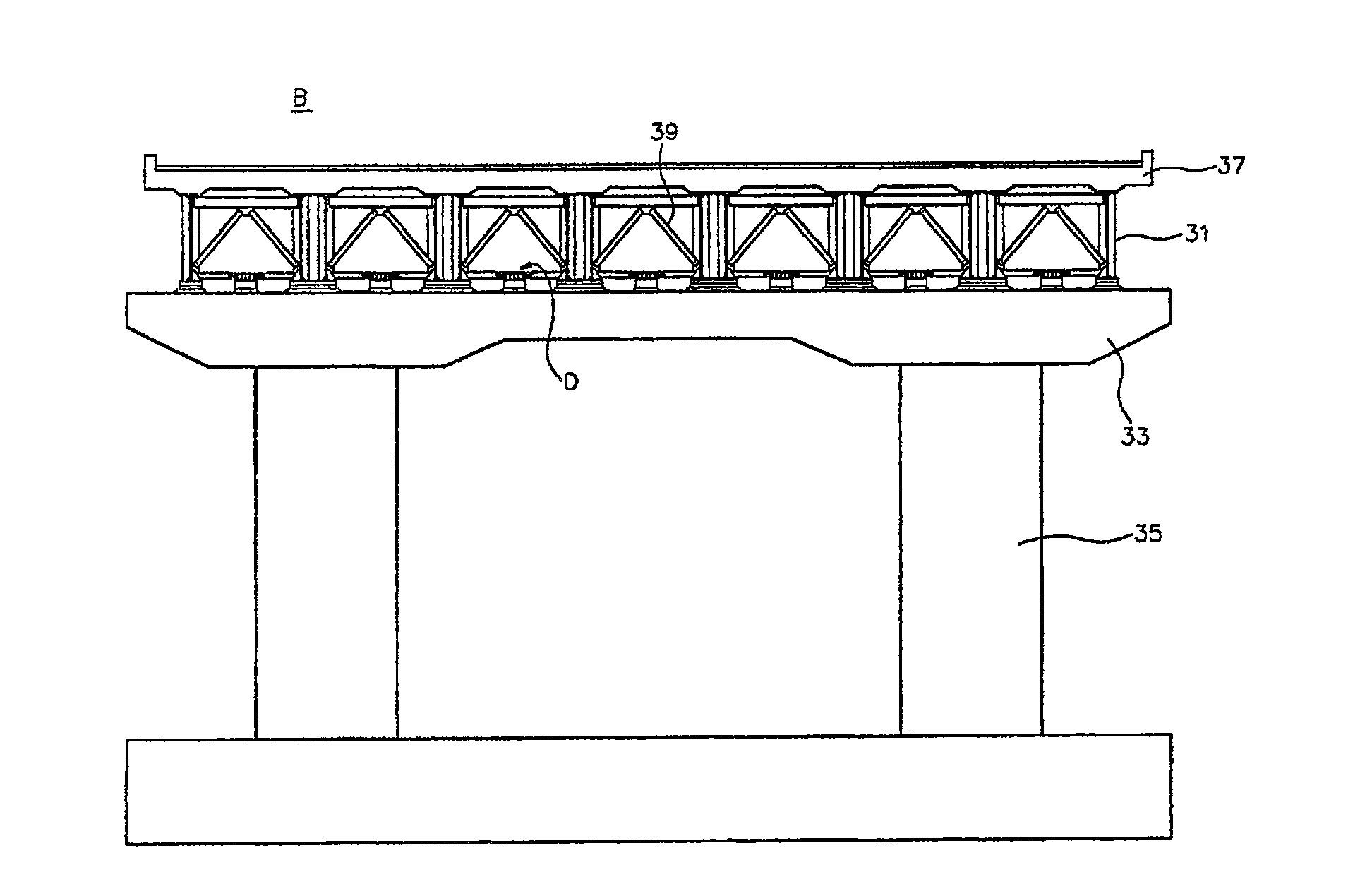
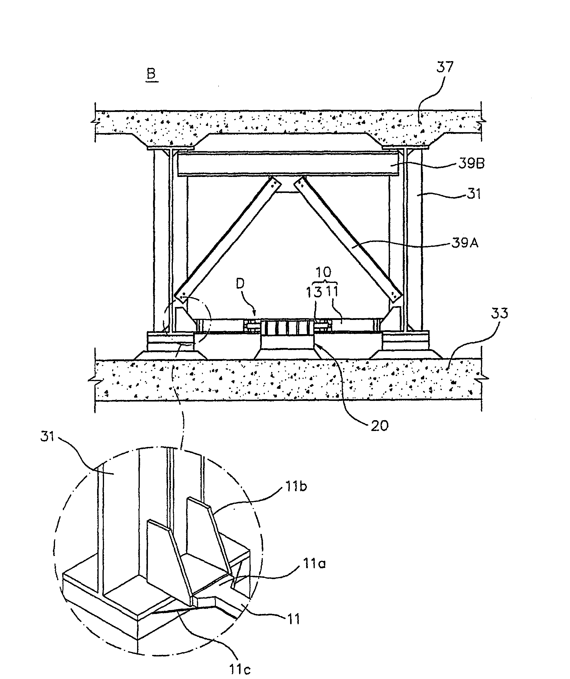
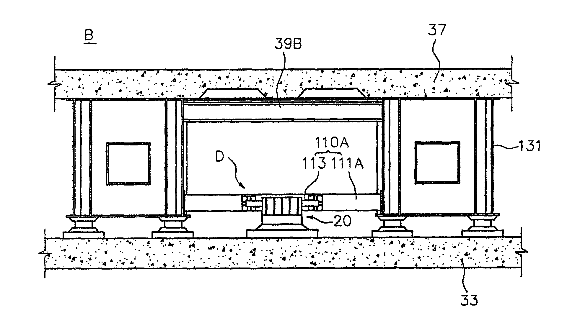
[0045] Before describing the bridge protection device according to the present invention, refer to Figure 1a with Figure 1b Follow the procedure below to set the orientation. The longitudinal direction of the superstructure connecting the piers positioned at both ends of the bridge B, tha...


PUM


Abstract

An girder bridge protection device comprises sacrifice means including girders which are installed on an upper surface of a bridge seat of an abutment or pier to support a bridge floor, a symmetricalmain support member which connects two girders and has a pipe-shaped configuration, and an auxiliary support member which projects from one surface of a center portion of the main support member in adirection perpendicular to an axial direction of the main support member; and restraining means secured to the bridge seat of the abutment or pier and including an accommodating section which accommodates the auxiliary support member such that the auxiliary support member is separated from the accommodating section in a forward and rearward direction and in a leftward and rightward direction, thereby controlling the behavior of the auxiliary support member.

Description

technical field [0001] The present invention relates generally to a device for protecting a bridge, and more particularly to a bridge protection device utilizing sacrifice means that support the loads normally imposed on the bridge and that, when seismic loads are applied The energy is then dissipated by sacrificing the plastic behavior induced by the main supports of the symmetrical structure, thereby protecting the remaining main components of the bridge. Background technique [0002] In this specification, a sacrificial part is a part applying the principle of a passive energy dissipation device. This part serves as a structural aid when no earthquakes occur. This component acts to passively dissipate energy generated on the structural member when seismic loads are applied, thereby improving bridge performance. [0003] Registered in Korea Utility Model No. 217048 "Device for Preventing Separation of Main Structure from Continuous Steel Box Bridge" (January 5, 2001) and...

Claims


Application Information

Patent Timeline
Patent Type & Authority Patents(China)
IPC IPC(8): E01D19/00
CPCE01D19/00
Inventor 金相孝
Owner 延世产学协力团
Why Eureka
Try Eureka