Light source device used for ship indication

A light source device and indicating technology, applied in the field of lighting optics, can solve the problems of easy generation of vignetting, uncontrollable angle, poor complementarity of luminous brightness, etc., and achieve the effects of strong resolution, simple and reliable structure, and uniform luminescence.

Inactive Publication Date: 2008-01-23
CHANGCHUN INST OF OPTICS FINE MECHANICS & PHYSICS CHINESE ACAD OF SCI
View PDF1 Cites 4 Cited by
  • Summary
  • Abstract
  • Description
  • Claims
  • Application Information

AI Technical Summary

Problems solved by technology

[0003] The known Chinese utility model patent No. 200320115436 discloses a "light-emitting diode integrated navigation light source", which solves the problem that the angle between the tubes and the tubes arranged in a circle is 45 degrees, which makes the complementary a

Method used


Image

  • Light source device used for ship indication

Examples


Embodiment Construction

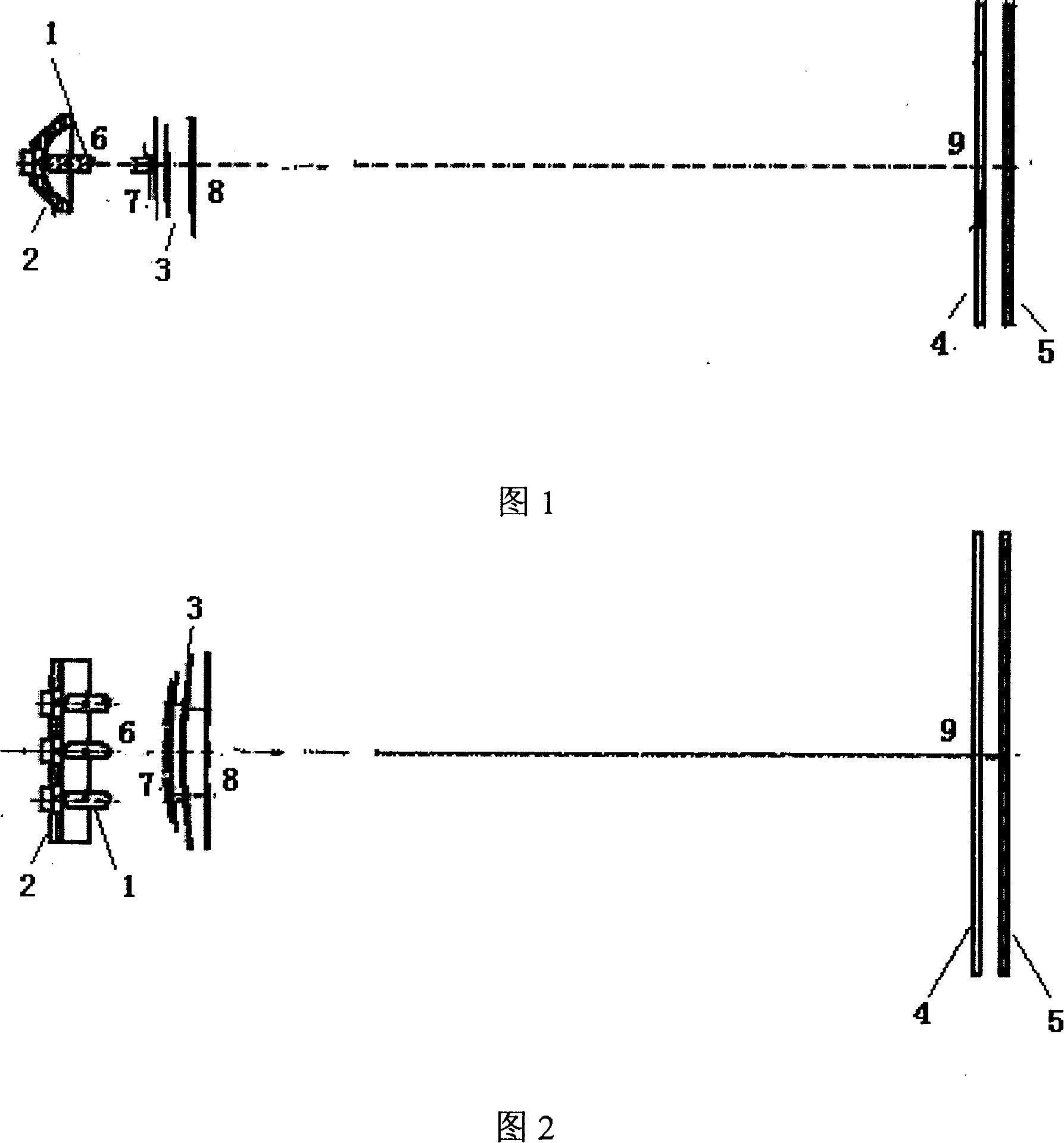
[0013] According to accompanying drawings 1 and 2, a halogen light source 1, an ellipsoidal reflective bowl 2, a slit group 3, a Fresnel lens 4, and a cylindrical mirror array 5 are installed on the same optical axis. The halogen light source 1 adopts three light sources placed horizontally side by side. The halogen light source 1 is located at the focal position 6 of the ellipsoidal reflective bowl 2, the slit group 3 is located at the other focal position 7 of the ellipsoidal reflective bowl, and at the same time is located at the focal plane position 8 of the Fresnel lens 4, and the Fresnel lens is located on the cylindrical surface The focal plane position 9 of the mirror array.

[0014] In Fig. 1, the light emitted from the halogen light source 1 concentrates the energy of the light source through the ellipsoidal reflective bowl 2, and by adjusting the distance between the slit 3, the Fresnel lens 4 and the cylindrical mirror array 5, according to the design requirements,...


PUM


Abstract

The invention pertains to the technical field of illumination optics, relates to an illuminant arrangement using a halogen lamp as light source, concentrating energy by a elliptic spherical reflecting mirror, and controlling the divergent angle of light beam by a Fresnel lens and a cylindrical mirror array. The invention comprises a halogen lamp, a elliptic spherical reflecting bowl, a slit group, a Fresnel lens, and a cylindrical mirror array. The elliptic spherical reflecting mirror is used for concentrating energy, the combination of the Fresnel lens and the cylindrical mirror array has not only guaranteed the full evening of light of the outgoing light beam in horizontal and vertical direction, but also guaranteed the outgoing angle; by the elliptic spherical reflecting bowl, the energy loss in the light source is minimized, so most energy is concentrated on the slit, this guarantees that the outgoing beam from the light box is visible and the lamp color is identifiable in certain distance. The invention is of simple and reliable structure, high operability, can be applicable for carrier-borne indication and the landing-assistant system for flying.

Description

1. Technical field [0001] The invention belongs to the technical field of lighting optics and relates to a ship indicating light source device. 2. Background technology: [0002] When the ship is sailing on the water, in addition to the modern communication means such as radio communication, the traditional light language plays an irreplaceable role in the transmission of information and orders. With the development of marine modernization, light signals still play a very important role in the communication between ships and between ships and carrier-based aircraft. Throughout the navies of various countries, while vigorously developing radio technology and communication, they still attach great importance to the research and development of traditional shipboard light box technology. At present, there are relatively standardized requirements for the emission angle and service life of shipboard light boxes in the world. In order to catch up with the international level as s...

Claims


Application Information

Patent Timeline
IPC IPC(8): F21S6/00F21V14/00F21W111/043
Inventor 张新崔继承丛小杰
Owner CHANGCHUN INST OF OPTICS FINE MECHANICS & PHYSICS CHINESE ACAD OF SCI
Why Eureka
Try Eureka