System, equipment and method for protecting link circuit

A technology for protecting links and equipment, applied in the field of communication, can solve the problems of occupying bandwidth, increasing protocol overhead, and high requirements for PE equipment, and achieving the effect of saving bandwidth, improving efficiency and reliability

Inactive Publication Date: 2008-07-23
HUAWEI TECH CO LTD
View PDF0 Cites 39 Cited by
  • Summary
  • Abstract
  • Description
  • Claims
  • Application Information

AI Technical Summary

Problems solved by technology

[0005] When adopting the first protection mode, the PE device needs to be able to support the TE FRR protocol, and running the TE FRR protocol increases the protocol overhead, and the requirements for the PE device are relatively high; in addition, the switch does not have the TE FRR capability. Unable to protect the link between the PE and the switch
When the second protection method is ad

Method used


Image

  • System, equipment and method for protecting link circuit
  • System, equipment and method for protecting link circuit
  • System, equipment and method for protecting link circuit

Examples


Embodiment 1

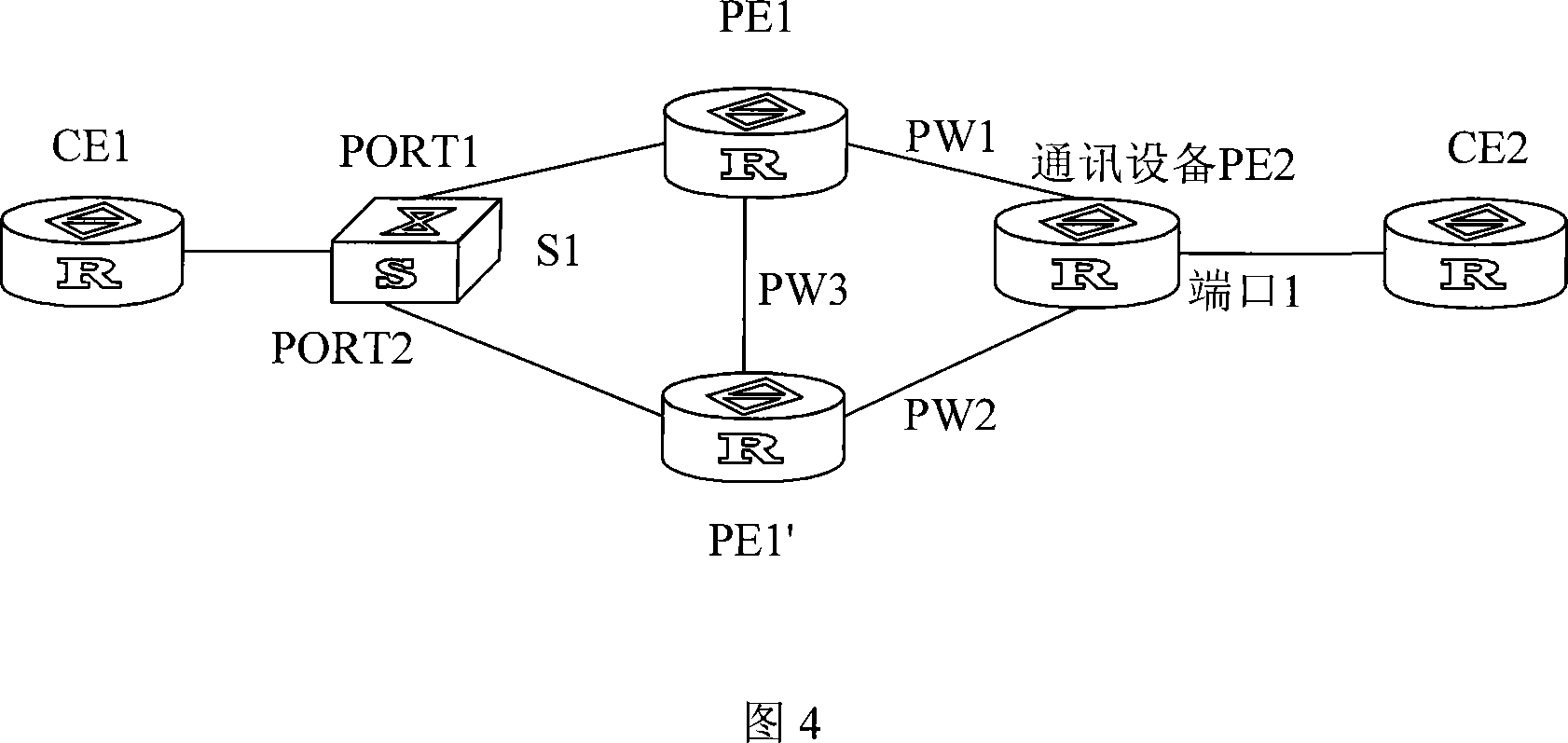
[0030] Referring to FIG. 3 , an embodiment of the present invention provides a method for protecting a link, which is applied to a multi-homing network. In this embodiment, the network in FIG. 4 is used as an example for illustration. Referring to FIG. 4 , the communication device is PE2, and PE2 is respectively connected to CE2, PE1 and PE1', PE1 is the first PE, and PE1' is the second PE; the method specifically includes:

[0031] 101: Establish a pseudo-wire PW1 between PE1 and PE2, and use PW1 as the first channel, and establish a pseudo-wire PW2 between PE1' and PE2, and use PW2 as the second channel.

[0032] 102: On PE2, bundle the pseudowires PW1 and PW2 corresponding to port 1 connected to CE2 together to obtain a pseudowire bundle group.

[0033] Multiple pseudowire bundle groups can be established on PE2, and each pseudowire bundle group includes at least two pseudowires.

[0034] In the embodiment of the present invention, after the pseudowire binding group is est...

Embodiment 2

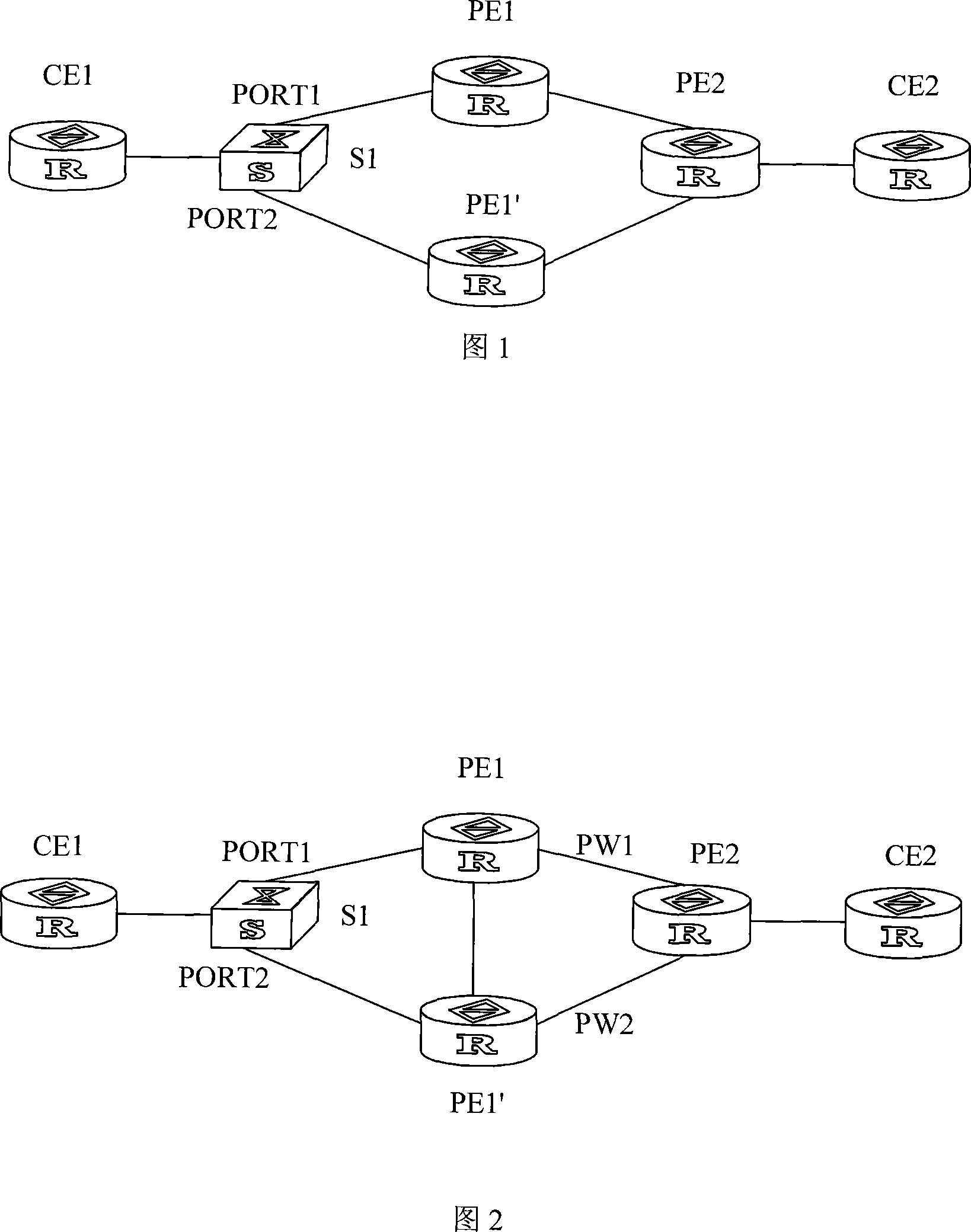
[0050] Referring to FIG. 5, the embodiment of the present invention also provides a method for protecting links, which is applied to a multi-homing network. In this embodiment, the network in FIG. 6 is used as an example for illustration. Referring to FIG. 6, the communication device is a switch S1 , and S1 is respectively connected to CE1, PE1 and PE1', PE1 is the first PE, and PE1' is the second PE; the method specifically includes:

[0051] 201: The link between S1 and PE1 is used as the first channel, the port connected to the first channel on S1 is PORT1, the link between S1 and PE1' is used as the second channel, and S1 is connected to the second channel The port is PORT2.

[0052] 202: On S1, bind PORT1 and PORT2 together in a manner symmetrical to the pseudowire binding group established by PE2 to obtain a port binding group. In this embodiment, the pseudowire binding group established by PE2 includes PW1 and PW2.

[0053] The symmetrical relationship between the pseu...

Embodiment 3

[0069] An embodiment of the present invention provides a device for protecting a link. The device is respectively connected to PEs and edge communication devices, and the edge communication device is connected to CE. The device includes:

[0070] The first processing module is used to forward the received message sent to CE to PE through the backup pseudowire associated with the channel when the channel between the edge communication device fails, and the backup pseudowire is located between the device and the PE between;

[0071] The second processing module is configured to forward the message to the edge communication device through the channel after receiving the message from the backup pseudowire.

[0072] Further, the above equipment also includes:

[0073] Establish a module for establishing a backup pseudowire between the device and the PE;

[0074] The association module is used to establish the association relationship between the backup pseudowire and the channel ...


PUM


Abstract

The invention discloses a method, equipment and a system for protecting link circuit, which belongs to the technical field of communication. The method is applied in a multi-ownership network which comprises communication equipment and a first PE and a second PE which are connected with the communication equipment, the method specifically comprises when faults exist on a first channel between the communication equipment and the first PE, the first PE transmits received message which is sent to CE to the second PE through a spare pseudo wire which is connected with the first channel and is located between the first PE and the second PE, the message is transmitted to communication equipment through a second channel which is connected with the spare pseudo wire and is located between the communication equipment and the second PE after being received by the PE. The equipment comprises a first processing module and a second processing module. The system at least comprises a first PE, a second PE and communication equipment. The invention achieves the protection of a link circuit, which lowers request to PE equipment, can not cause a great amount of broadcast flow quantity instantly, saves band width, shortens fault restoring time of systems, and improves efficiency and reliability.

Description

technical field [0001] The present invention relates to the technical field of communication, in particular to a method, device and system for protecting a link. Background technique [0002] In L2VPN (Layer 2 Virtual Private Network, Layer 2 virtual private network), service providers use VPLS (Virtual Private Lan Service, virtual private LAN service) technology or MPLS (Multiprotocol Label Switch, multi-protocol label switching) technology to provide users with Ethernet-based multipoint services. At present, the telecommunication network puts forward higher and higher requirements for transmission reliability. CE (Customer Edge Device, user network edge device) dual-homing technology is a solution proposed to meet high reliability. Referring to Figure 1, CE1 is connected to switch S1, S1 is connected to PE (Provider Edge Device, operator network edge device) 1 through port PORT1, and connected to PE1' through port PORT2, both PE1 and PE1' are connected to PE2, PE2 and CE2...

Claims


Application Information

Patent Timeline
IPC IPC(8): H04L12/56H04L12/28H04L45/28
Inventor 石悌君汪韵瑶王科吴明宋真庆庞立祥王娟
Owner HUAWEI TECH CO LTD
Why Eureka
Try Eureka