Optical packet head and payload separation structure used in asynchronous optical packet switching network

A technology of optical packet switching and separation structure, which is applied in the direction of data switching network, star electromagnetic network, electromagnetic network arrangement, etc. It can solve the problems of unreachable switch ratio, synchronization limitation, expandability and application range, etc., and reduce production cost. requirements, low power consumption, and easy-to-achieve effects

Inactive Publication Date: 2008-09-24
SOUTHEAST UNIV
View PDF0 Cites 4 Cited by
  • Summary
  • Abstract
  • Description
  • Claims
  • Application Information

AI Technical Summary

Problems solved by technology

Although these solutions can realize the extraction of optical packet headers, their complexity and synchronization will limit their scalability and application range
Also, the on-off ratio cannot reach a very high level

Method used


Image

  • Optical packet head and payload separation structure used in asynchronous optical packet switching network
  • Optical packet head and payload separation structure used in asynchronous optical packet switching network
  • Optical packet head and payload separation structure used in asynchronous optical packet switching network

Examples


Embodiment Construction

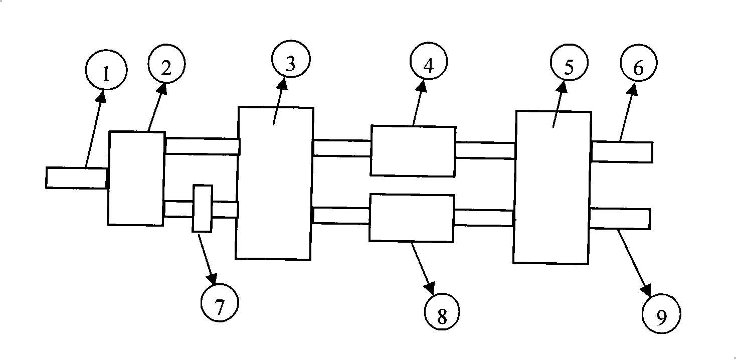
[0030] An optical packet header and payload separation structure used in an asynchronous optical packet switching network is characterized by comprising: an optical power splitter 2 and a second multimode interference coupler 5, on the upper output port of the optical power splitter 2 Connected with the first multimode interference coupler 3 and the upper output port of the optical power splitter 2 is connected with an input end of the first multimode interference coupler 3, and the lower output port of the optical power splitter 2 passes through the fiber delay line 7 Be connected with another input end of the first multimode interference coupler 3, an output end of the first multimode interference coupler 3 is connected with an input end of the second multimode interference coupler 5 through the first semiconductor optical amplifier 4, The other output end of the first multimode interference coupler 3 is connected with the other input end of the second multimode interference ...


PUM


Abstract

The invention relates to a separation structure of optical packet heads and payload used in an asynchronous optical packet switching network, and is characterized in that: the structure comprises an optical power splitter and a second multimode interference coupler; an upper output port of the optical power splitter is connected with a first multimode interference coupler and the upper output port of the optical power splitter is connected with an input end of the first multimode interference coupler; a lower output port of the optical power splitter is connected with the other input end of the first multimode interference coupler through an optical fiber delay line; an output end of the first multimode interference coupler is connected with an input end of the second multimode interference coupler through a first semiconductor optical amplifier; the other output end of the first multimode interference coupler is connected with the other input end of the second multimode interference coupler through a second semiconductor optical amplifier; detection optical packet heads are outputted from a lower output port of the second multimode interference coupler; the detection optical payload is outputted from an upper output port of the second multimode interference coupler.

Description

technical field [0001] The invention relates to an all-optical packet header and payload separation structure, in particular to an optical packet header and payload separation structure used in an asynchronous optical packet switching network. The invention can be used in high-speed optical transmission links to realize the separation of packet headers (ie address codes) and payloads (ie data) in optical packets. technical background [0002] The optical packet switching technology (The optical packet switching OPS) is considered to be the most promising switching technology in the third generation optical network. Due to the lack of optical RAM technology, all-optical routing has become an important bottleneck in the development of optical networks. But on the other hand, all-optical routers can be developed to realize switching and competition mechanisms in the wavelength domain, and at the same time can realize high-speed multi-wavelength signal transmission under the co...

Claims


Application Information

Patent Timeline
Patent Type & Authority Applications(China)
IPC IPC(8): H04Q11/00H04Q3/52H04B10/207H04L12/56H04B10/272
Inventor 孙小菡赵俊邵宗彪
Owner SOUTHEAST UNIV
Why Eureka
Try Eureka