LCD device

A liquid crystal display device, LED drive technology, applied to static indicators, instruments, etc., can solve the problem of discrete LED parameters

Inactive Publication Date: 2008-12-24
孙金龙
View PDF1 Cites 10 Cited by
  • Summary
  • Abstract
  • Description
  • Claims
  • Application Information

AI Technical Summary

Problems solved by technology

[0007] In order to solve the deficiencies in the prior art, the embodiment of the present invention particularly provides a liquid crystal display device, which uses the method that each output c

Method used


Image

  • LCD device
  • LCD device
  • LCD device

Examples


Embodiment 1

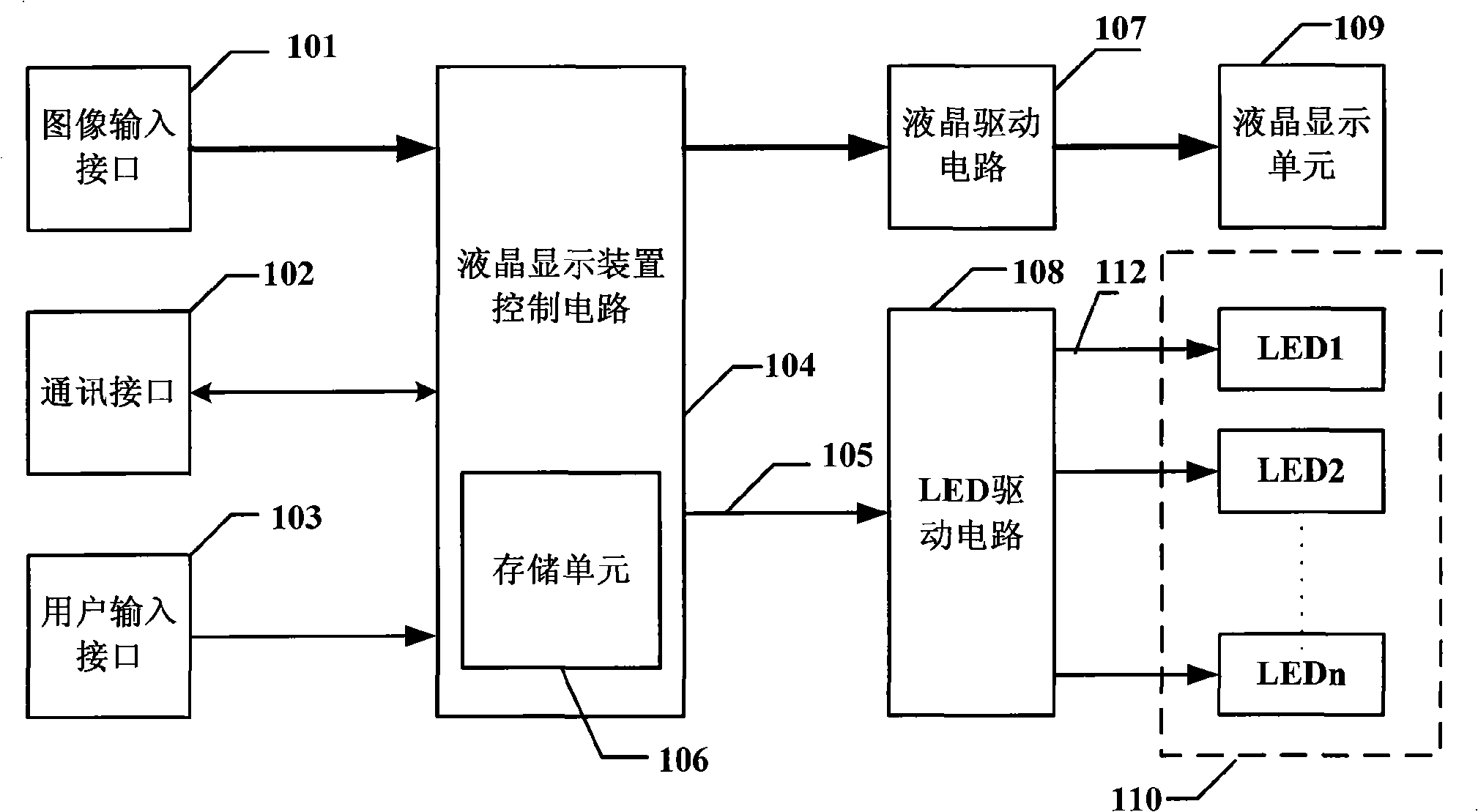
[0032] refer to figure 1 , figure 2 As shown, the liquid crystal display device includes: an image input interface 101, which receives an image signal and sends it to the control circuit 104 of the liquid crystal display device for processing; a communication interface 102, which is used for mutual communication between the liquid crystal display device and the host computer; a user input interface 103, It is used for the user to control the liquid crystal display device; the control circuit 104, on the one hand, receives image input and user input, generates driving signals for controlling the liquid crystal drive circuit 107 and the LED drive circuit 108, and on the other hand, communicates with the host through the communication interface, and accepts the control of the host; The storage unit 106 stores the adjustment parameters set by the host computer to the LED backlight assembly 110; the liquid crystal drive circuit 107 receives the liquid crystal control signal from t...

Embodiment 2

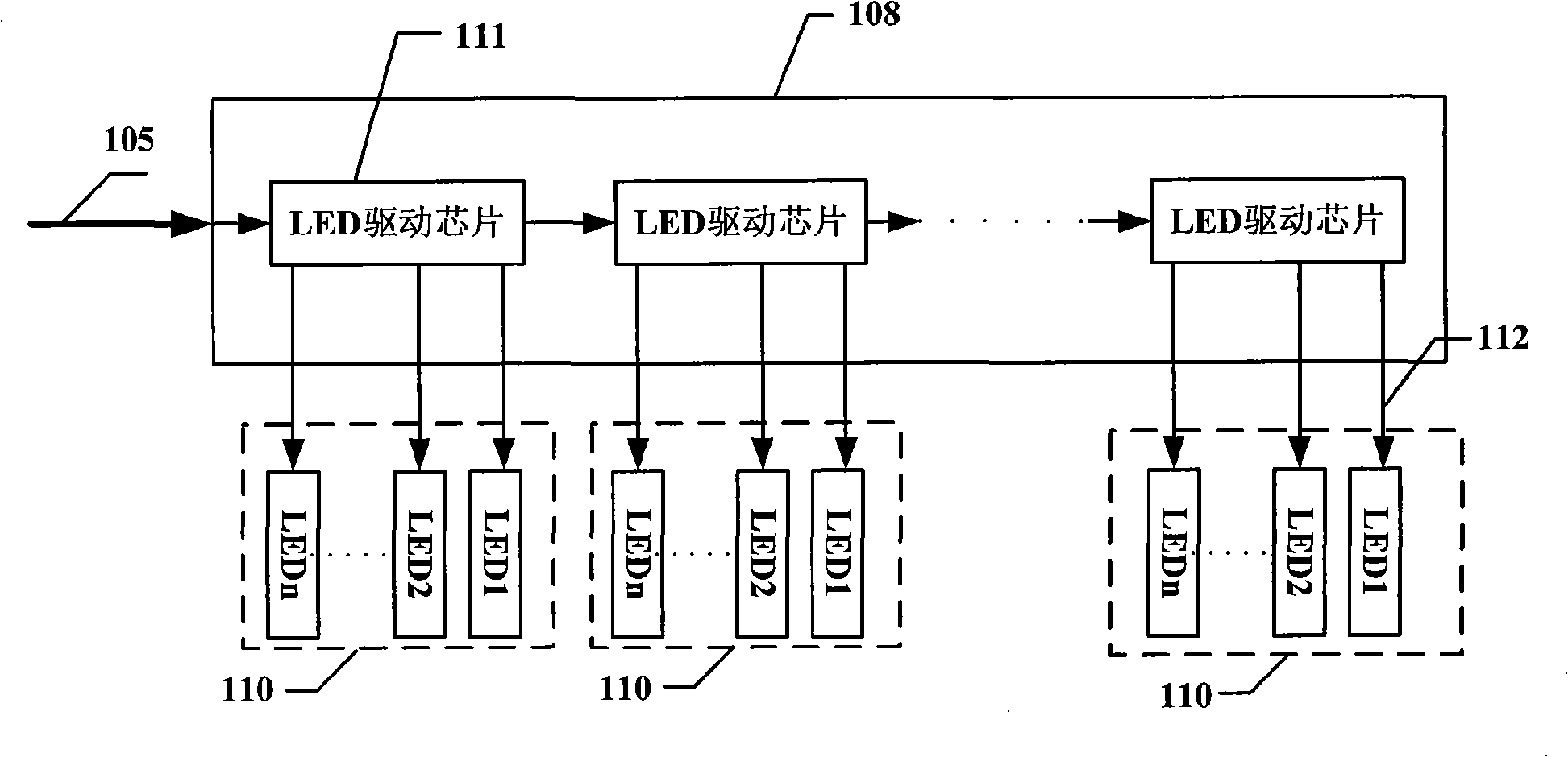
[0038] refer to figure 1 and Figure 4 As shown, the difference between this embodiment and Embodiment 1 is that the LED driving chips 111 in the LED driving circuit 108 are connected in parallel, and there is no mutual connection control signal between the driving chips, and the rest of the principles are the same as those of the first embodiment. I won't repeat them here.

Embodiment 3

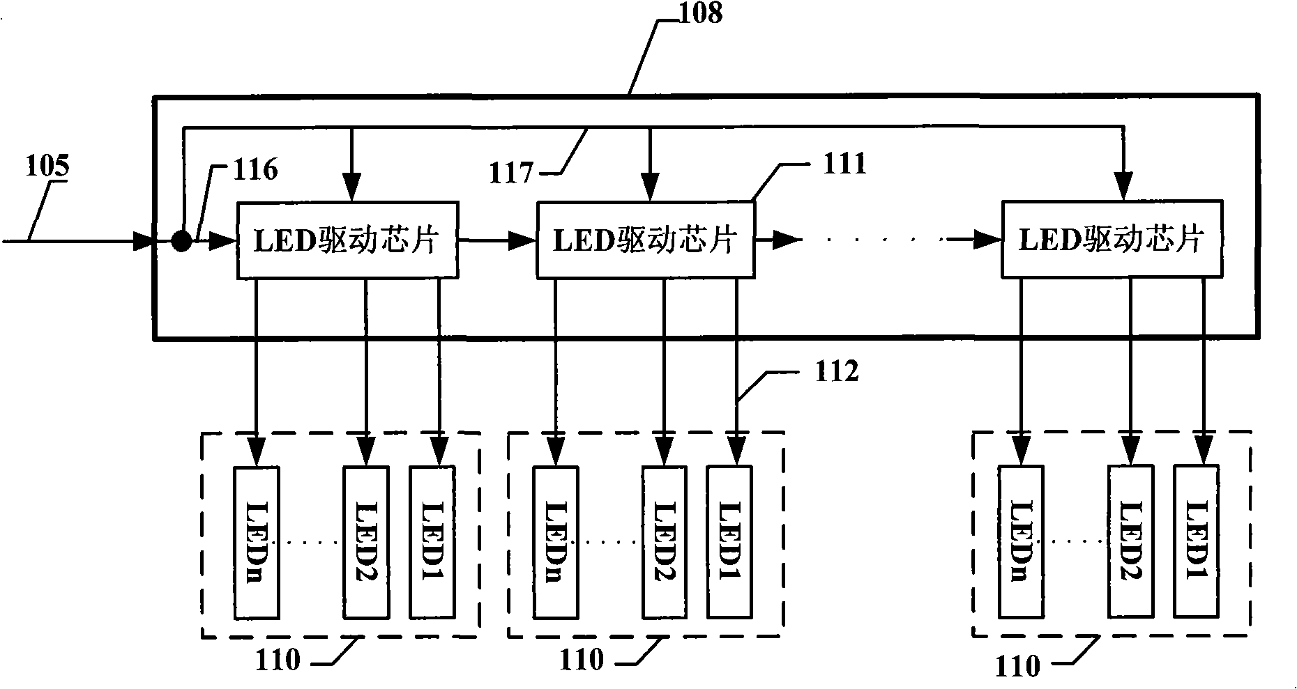
[0040] refer to figure 1 and image 3 As shown, the difference between this embodiment and Embodiment 1 is that the driving chip control signal 105 includes a control signal 116 and a data signal 117 .

[0041] The control signal 116 in the drive chip control signal 105 controls more than one LED drive chip 111 in the LED drive circuit 108 in a step-by-step serial manner, and the data signal 117 is sent to more than one LED drive chip 111 in the LED drive circuit 108 in a parallel manner. The LED driver chip 111 inputs data.

[0042] In addition, the connection mode between the control signal 116 and the data signal 117 and each driving chip 111 can also be that the control signal 116 in the driving chip control signal 105 controls more than one LED driving in the LED driving circuit 108 in parallel. chip 111 , the data signal 117 inputs data to more than one LED driving chip 111 in the LED driving circuit 108 in a serial manner.

[0043] The rest of the principles are the ...


PUM


Abstract

The invention relates to a liquid crystal display device which comprises an image input interface, a communication interface, a user input interface, a storage unit, a liquid crystal display device, a control circuit, a liquid crystal drive circuit, an LED drive circuit, a liquid crystal display unit and an LED backlight component. By utilizing the manner that every output control end of the LED drive unit is only connected with one LED, every LED is driven independently so as so solve the problem of parameter straggling of the LED.

Description

technical field [0001] The invention belongs to the technical field of liquid crystal display, in particular to a liquid crystal display device using LED as a backlight source. Background technique [0002] Currently, a liquid crystal display device is the most widely used flat panel display device. Since the liquid crystal display device is thinner and lighter than other display devices, it is widely used in notebook computers, mobile terminals, etc. A general liquid crystal display device includes an LCD panel assembly and a backlight assembly. [0003] The backlight assembly includes a light source for generating light and an optical member for improving brightness characteristics of light projected by the light source. In traditional liquid crystal display devices, cold cathode fluorescent lamps (CCFL) are usually used as backlight sources. However, due to problems such as difficult driving, short lifespan, and low energy efficiency, liquid crystal display devices using...

Claims


Application Information

Patent Timeline
IPC IPC(8): G09G3/36
Inventor 杨雷邵寅亮
Owner 孙金龙
Why Eureka
Try Eureka