Both-side driven rotary tillage soil-working machine

A technology of leveling machine and transmission box, which is applied in the fields of tillage equipment, transmission device, differential transmission device, etc., can solve the problems of increasing the torque of the side plate end of the knife roller, the easy bending and breaking of the knife roller, and the poor gluing performance of the gear, etc. The effect of good meshing performance, small machine vibration and balanced torque

Inactive Publication Date: 2009-01-07
常发成 +2
View PDF0 Cites 3 Cited by
  • Summary
  • Abstract
  • Description
  • Claims
  • Application Information

AI Technical Summary

Problems solved by technology

Its biggest advantage is that there is no soil and missing tillage in the middle of the cutter roller, and the flatness of the land preparation is also good. The disadvantage is that the end of the cutter roller with the side box is heavy, and the end with the side plate is light, and the weight of the whole machine is unbalanced. It is inclined, so the ground plane is inclined after rotary tillage; since the power to drive the cutter roller is completed by one side box, the design strength of the single side side box must meet the needs of the total load, and the gear modulus is large , and the large modulus gear has poor bonding performance, resulting in large noise, high impact force, high oil temperature, and easy damage to parts; unilateral drive increases the torque at the side plate end of the cutter roller, and the cutter roller is easy to bend and break

Method used


Image

  • Both-side driven rotary tillage soil-working machine
  • Both-side driven rotary tillage soil-working machine

Examples


Embodiment Construction

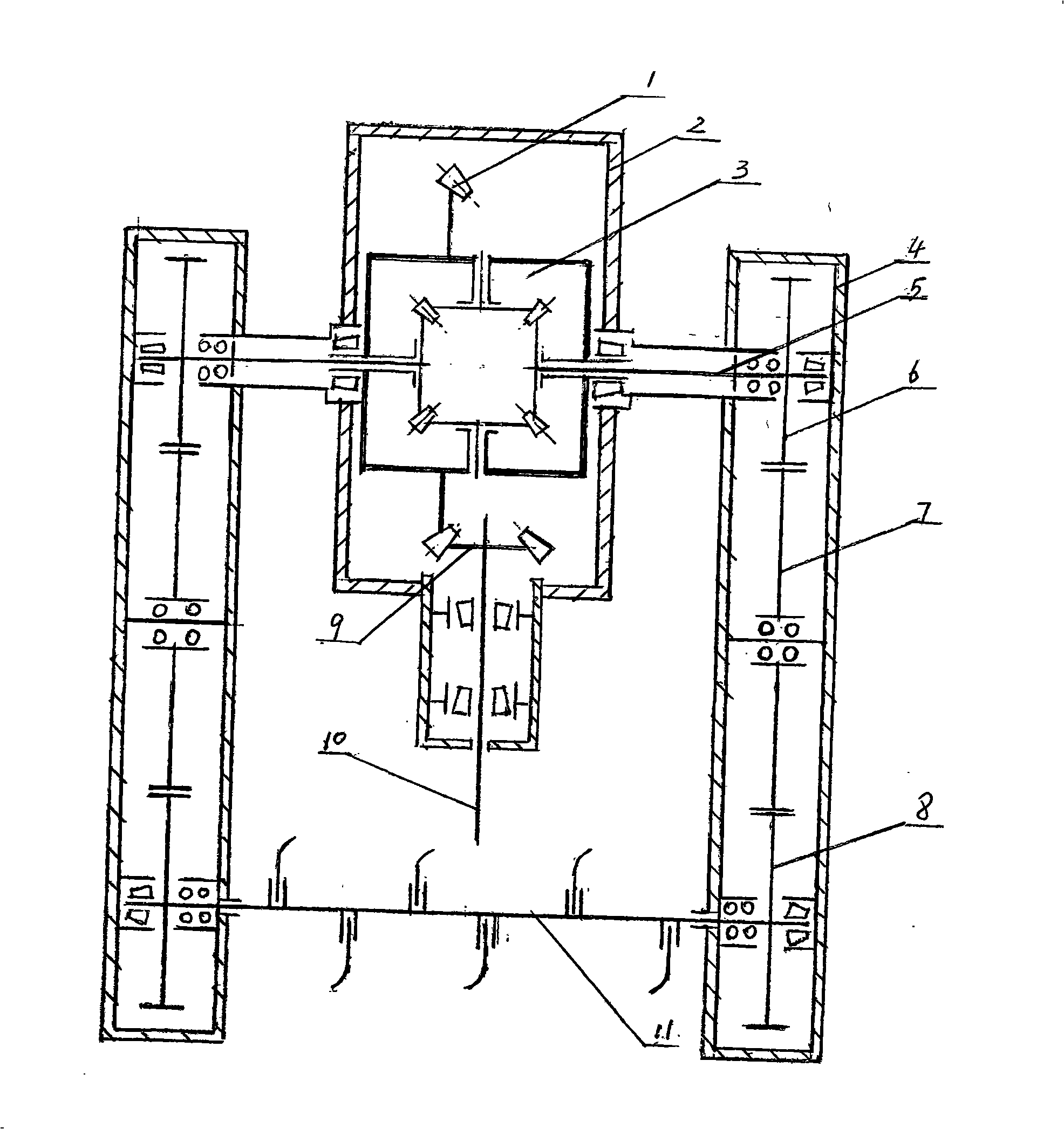
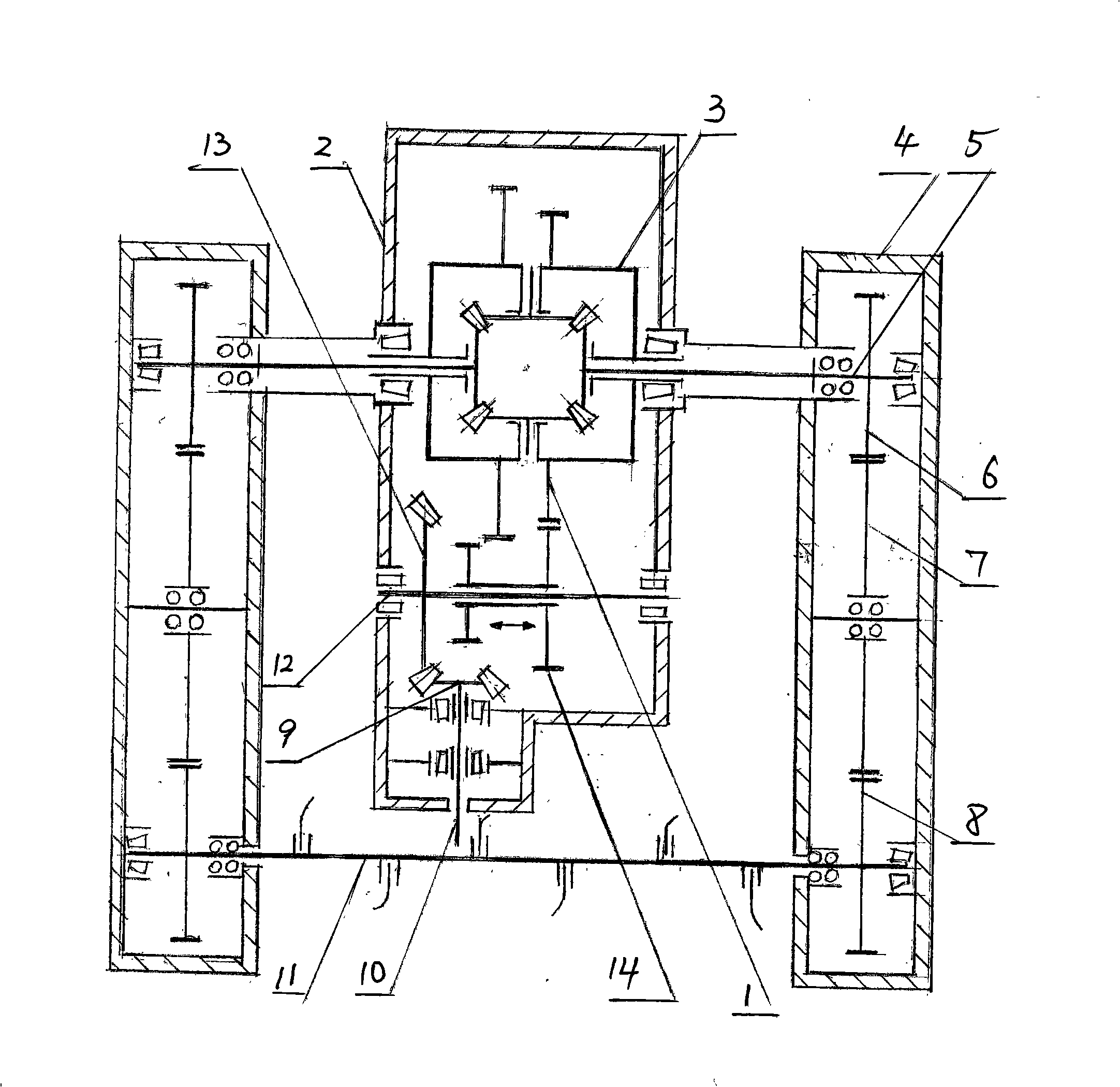
[0013] A two-sided transmission rotary tillage soil preparation machine, comprising a transmission assembly and a knife roller assembly 11. The transmission assembly includes a middle transmission box 2 and two left and right side transmission boxes 4 connected with the rear power output of the tractor through a universal joint. A pair of large and small bevel gears meshing with each other in the intermediate transmission box 2, the small bevel gear 9 is mounted on the power input shaft 10, the power input shaft 10 is connected with the rear power output of the tractor through a universal joint, and the large bevel gear is fixed in a differential The transmission gear 1 on the housing of the speed gear 3, the differential gear 3 is equipped with four bevel gears that mesh with each other perpendicularly, and the left and right bevel gears of the differential gear 3 are splined to one end of the left and right output shafts 5. The output half shafts 5 on both sides of the speed gea...


PUM


Abstract

Two-side-driven rotary tillage soil-preparing machine, comprising transmission assembly and knife roller assembly, wherein the transmission assembly comprises an intermediate transmission box and left and right two side transmission boxes. A power input shaft and a differential connected to rear power output of the tractor through cardan joint are fixed in the intermediate transmission box, wherein a transmission gear is fixed on casing of differential and an input bevel pinion is mounted on the power input shaft, and the transmission gear and the bevel pinion transmit through gears. The differential has a structure that four orthogonal angle gears are fixed in the casing, wherein each of the two angle gears at left and right is connected with an output half shaft respectively of which outer end is connected to a drive gear in each of the two side transmission boxes respectively. When tooth spaces of gears in the left and right two side transmission boxes are not on a same line, the two angle gears at left and right in the differential would be lightly turned under the action of torque to make the drive gears in the two side transmission boxes normally work, thereby making knife roller assembly normally rotate. The soil-preparing machine has the advantages of gravity balance in whole body, fine stability and flat ground surface after ploughing.

Description

Technical field [0001] The invention relates to a rotary tillage machine, in particular to a two-side transmission rotary tillage soil preparation machine integrating rotary tillage, stubble burying and harrowing. Background technique [0002] Land preparation with rotary tillage machinery is a mature technology, and it is also a machine commonly used in rural areas across the country. The machine is mainly divided into two categories: the middle box transmission knife roller and the side box transmission knife roller. The characteristic of the middle transmission is that the rotary tiller rollers are on both sides of the middle transmission box. In order to avoid the leakage of the lower part of the middle box, a small plowshare is specially installed. The small plowshare can only cultivate the land statically and has poor soil turning ability. It is easy to cause clogging and omission of soil under the middle box. The side transmission is driven by a transmission box arranged o...

Claims


Application Information

Patent Timeline
Patent Type & Authority Applications(China)
IPC IPC(8): A01B33/08A01B71/00F16H48/00F16H48/12F16H48/38
Inventor 蔡国芳常发成仲子堂胡传干史孝华
Owner 常发成
Why Eureka
Try Eureka