Integrated heat radiator of fine antipriming pipe parallel flow for automobile

A technology that integrates heat dissipation and multi-hole tubes, which is applied in the power unit, the arrangement of the cooling combination of the power unit, and vehicle components, etc. It can solve the problems of the destruction of the atmospheric ozone layer of the vehicle refrigerant, the inability of the refrigerant and the tube to heat, and the inability of the refrigerant to dissipate heat. , to achieve the effect of large price advantage, low production cost, and improved installation and maintenance efficiency

Inactive Publication Date: 2009-02-18
SOUTH CHINA UNIV OF TECH
View PDF0 Cites 8 Cited by
  • Summary
  • Abstract
  • Description
  • Claims
  • Application Information

AI Technical Summary

Problems solved by technology

They all exist independently in the vehicle and are installed in the engine compartment of the vehicle, so they all have their own shortcomings that are difficult to overcome: ①The condenser in the automobile air conditioning system, the water tank radiator in the engine cooling system, and the engine oil in the engine lubrication system The radiator, etc., occupy a large volume in the engine compartment, which will inevitably lead to a reduction in the cabin space; ②The existing automotive air-conditioning system condensers mainly have the following three structural forms, namely, tube-sheet type, tube-belt type, and stacked For vehicles using tube-fin condensers, severe bumps and vibrations will occur during driving, which will cause looseness between the tubes and fins, which will aggravate the reduction of heat transfer effect; while tube-belt or stacked condensers will be used. Vehicles with evaporators have low heat exchange efficiency due to their large size, heavy weight, insufficient cooling capacity, small effective heat dissipation area, and large wind resistance; ③ Leaked vehicle refrigerant (currentl

Method used


Image

  • Integrated heat radiator of fine antipriming pipe parallel flow for automobile
  • Integrated heat radiator of fine antipriming pipe parallel flow for automobile
  • Integrated heat radiator of fine antipriming pipe parallel flow for automobile

Examples


Example Embodiment

[0026] The present invention will be described in further detail below in conjunction with the accompanying drawings, but the embodiments of the present invention are not limited thereto.

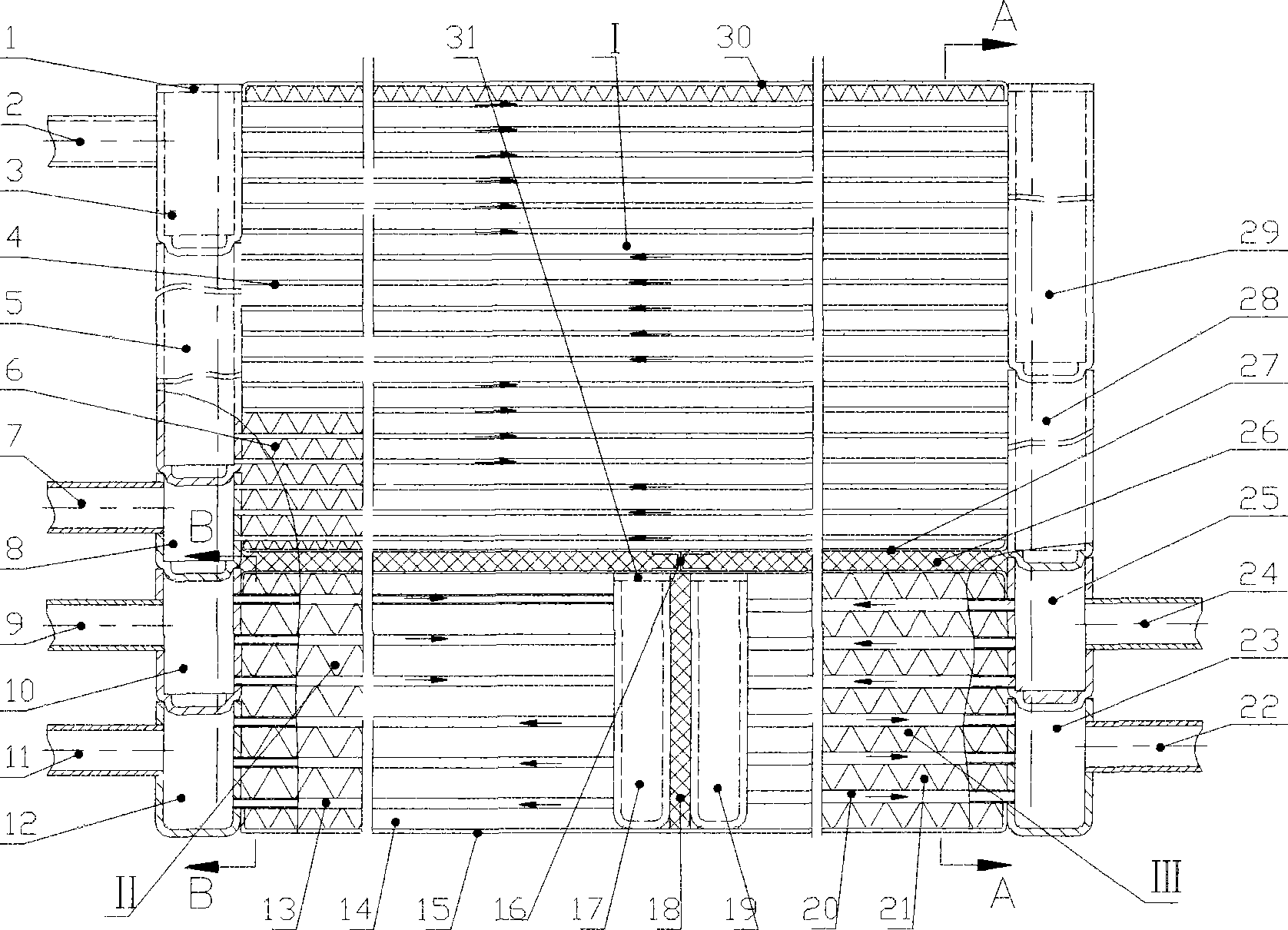
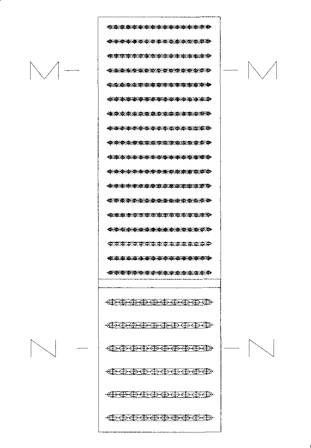
[0027] like figure 1 , 2 As shown in , 4, the micro-porous tube parallel flow integrated cooling device for automobiles includes an air-conditioning condenser I, a water tank radiator II and an engine oil cooler III, and the water tank radiator II and the engine oil cooler III are arranged side by side. The layers 18 are separated and are located at the lower end of the air-conditioning condenser I. The air-conditioning condenser I is separated from the water tank radiator II and the engine oil cooler III by the middle upper partition 27 and the middle lower partition 26. The middle upper partition 27 and the middle The lower partition 26 is fixed by the I-shaped bracket 16 .

[0028] The air conditioner condenser I is mainly composed of one of the header end covers 1, CO 2 (R744) (R744—...


PUM

PropertyMeasurementUnit
Apertureaaaaaaaaaa

Abstract

The invention discloses a parallel flow integrated heat sink for superfine perforated pipes in a motor vehicle, which comprises an air-conditioning condenser, a water tank radiator and an engine oil cooler, wherein the water tank radiator and the engine oil cooler are arranged in parallel from side to side, separated by a heat-insulating layer, and positioned on the lower end of the air-conditioning condenser together; both ends of the air-conditioning condenser are provided with flow concentrating sections; a plurality of rows of the superfine perforated pipes are connected among the flow concentrating sections; wavy radiating fins are clamped between two rows of the superfine perforated pipes and respectively welded with one row of the superfine perforated pipes; a CO2 (R744) coolant gas-phase inlet pipe and a CO2 (R744) coolant gas-phase outlet pipe are respectively connected to the flow concentrating sections; and the flow concentrating sections on both ends are a plurality of sleeved structures capable of being arranged in the forward direction. The parallel flow integrated heat sink for the superfine perforated pipes in the motor vehicle integrates condensation of the prior vehicle air-conditioner, heat dissipation of a water tank and cooling of engine oil, is modularized, has light the overall mass and small occupied space, and adopts a multivariated parallel flow condenser and a segmented collecting pipe of the multivariated parallel flow condenser, so that refrigerant can flow to and fro for a plurality of times in the condenser and the heat exchange ability is strong.

Description

technical field [0001] The invention relates to a cooling device for a vehicle, in particular to a microporous tube parallel-flow integrated cooling device for a vehicle. The device includes heat exchange components such as air-conditioning condensation, water tank heat dissipation, engine oil cooling, etc. in the form of parallel flow made of micro porous tubes (microchannels) and collecting pipes (sections). Background technique [0002] There are heat exchange devices with different functions and forms in various vehicles, such as condensers in automotive air-conditioning systems, water tank radiators in engine cooling systems, and oil radiators in engine lubrication systems. They all exist independently in the vehicle and are installed in the engine compartment of the vehicle, so they all have their own shortcomings that are difficult to overcome: ①The condenser in the automobile air conditioning system, the water tank radiator in the engine cooling system, and the engin...

Claims


Application Information

Patent Timeline
IPC IPC(8): B60K11/04B60H1/32
Inventor 梁荣光何冰强向丹巫江虹
Owner SOUTH CHINA UNIV OF TECH
Why Eureka
Try Eureka